Ultra-cut 300 xt, Mc2a mc2b, Fan1 – Tweco 300 XT Ultra-Cut Plasma Cutting System User Manual
Page 178
ULTRA-CUT 300 XT
�7�
PPENDIX
Manual 0�5�7�
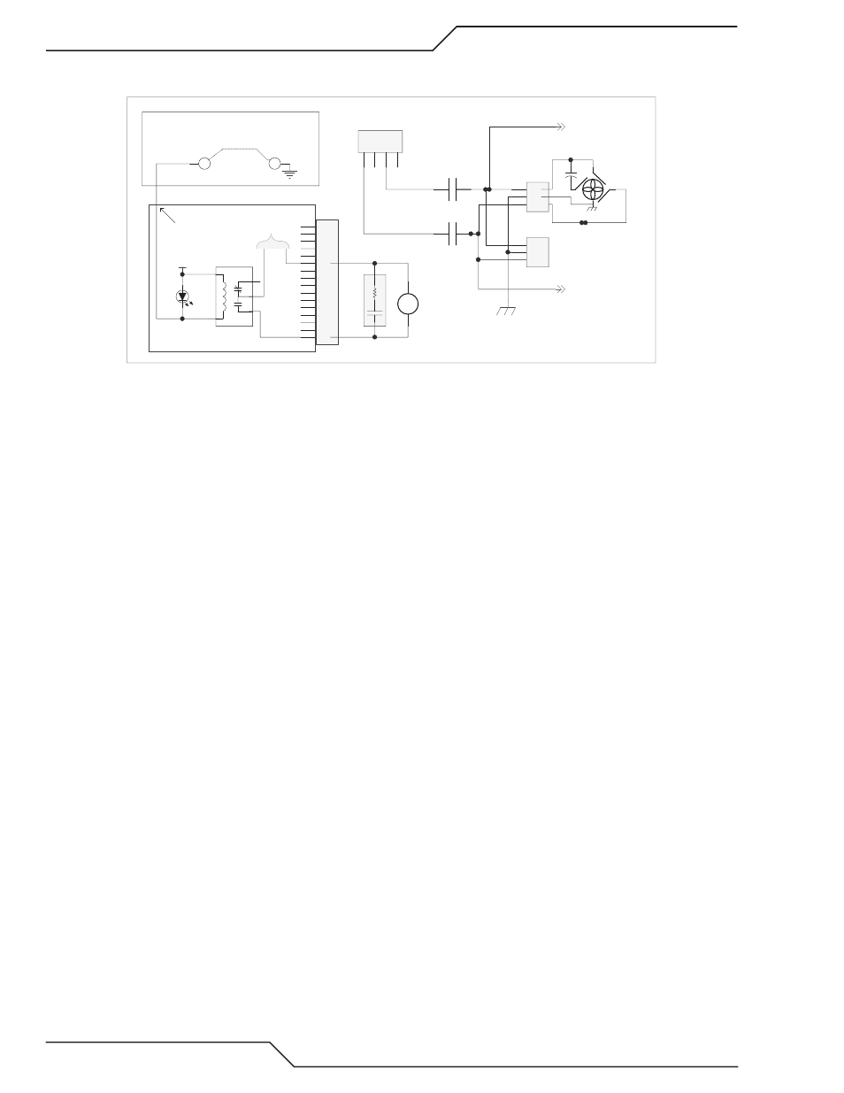
�. Fans are powered by �30 VC. The �30 VC for the fan(s) is switched by the MC� control relay (except the
C �00 XT where the fan(s) is powered directly from the T1 transformer at J13).
Art # 12311
1
2
3
4
5
6
7
8
9
10
11
12
13
14
15
16
J8
1
5
3
2
4
Fan Bias Control
K4
MC2
Fan Control
(160)
(161)
SA3
ARC_SUPPRESSOR
D24
24 VAC
Relay PCB
230 VAC from T1
MC2A
MC2B
To J70-2
To J70-3
(69)
(70)
(70)
(65A)
(70)
(69)
1
2
3
J73
(64A)
CHASSIS GND
1
2
3
J72
C4
FAN1
R
R
BK
BN
BL
1
2
3
4
J13
TP1
TP2
CCM I/O PCB
To test fan relay jump TP2 to TP1.
+24
J4-19
3. Check for �30 VC at either of the fan connectors, J7� & J73. It may also be measured at the rear panel con�
nector J70 for the HE�00XT fan.
a. If the fans are not getting �30 VC, measure for �� VC on the coil of MC�. If present and the relay
contacts aren’t closed the relay is defective. Note, the coil is rectified so you won’t measure continuity
of even a good coil.
b. If �� VC is not on the MC� coil check for D�� on the relay board being ON. If it’s on, the Relay board
should be providing the �� VC so if it’s not the Relay board must be defective.
c. If D�� is not on, measure on the CCM I/O board between TP� and the common at TP1. It should be low,
near zero volts. If not the CCM is probably defective. Jumper TP� (I/O board) to TP1. If the fans now
come on replace the CCM.
d. If jumping TP� to TP1 does not turn the fans on then the Relay board or the �0 pin ribbon cable pin 19
is at fault.
404
Coolant System Not Ready
When power is applied to the system with External Plasma Enable satisfied and Plasma Power Supply Enabled
(switch on �010 or TSC 3000), assuming there is enough coolant in the tank, after some initial tests taking about
15��0 seconds (see manual section � for details of the Start�Up Sequence) the pump will start. Coolant will be
pumped through the system. Flow is measured by the FS1 flow switch placed in the torch coolant return path
just before the radiator (see plumbing diagram). If the flow doesn’t reach at least 0.75 GPM (�.8 lpm) within
� minutes it will set the �0� fault. The reason for the � minutes is a new dry system especially one with long
torch leads will take some time before the leads, hoses, radiator and cold plates are full of coolant. More coolant
may have to be added. On a system that has been run before it normally takes only a few seconds to establish
proper flow. In any case the pump will run for � minutes before setting the �0� fault.
First determine if the pump motor is running and if so is there any coolant flowing. With the right lower side
panel removed touch the pump and feel for vibration to indicate if the motor is running. Observe the clear
coolant hoses to see if they are full of coolant. There are two hose fittings on the back of the tank. The upper
one is the coolant return. Remove the tank filler cover. You should see a fairly strong stream of coolant from
that fitting. The lower fitting is from the pump bypass valve. If the pump is operating some coolant may be
exiting that fitting as well. If these fittings are below the coolant level you may have to drain out some of the
coolant to see this. If a strong stream is exiting the bypass (lower) fitting but nothing from the upper fitting,
you probably have some kind of blockage.