Ultra-cut 300 xt – Tweco 300 XT Ultra-Cut Plasma Cutting System User Manual
Page 161
ULTRA-CUT 300 XT
Manual 0�5�7�
PPENDIX
�55
PWR Present
• When power is first applied to the inverter (contactor closed) CCM checks for presence of the +12V bias
on the Inverter Control and Fault board. If not present will set codes in the range of �65��70.
IS_ID (A, B, or C)
VAC_SEL (A or B)
201
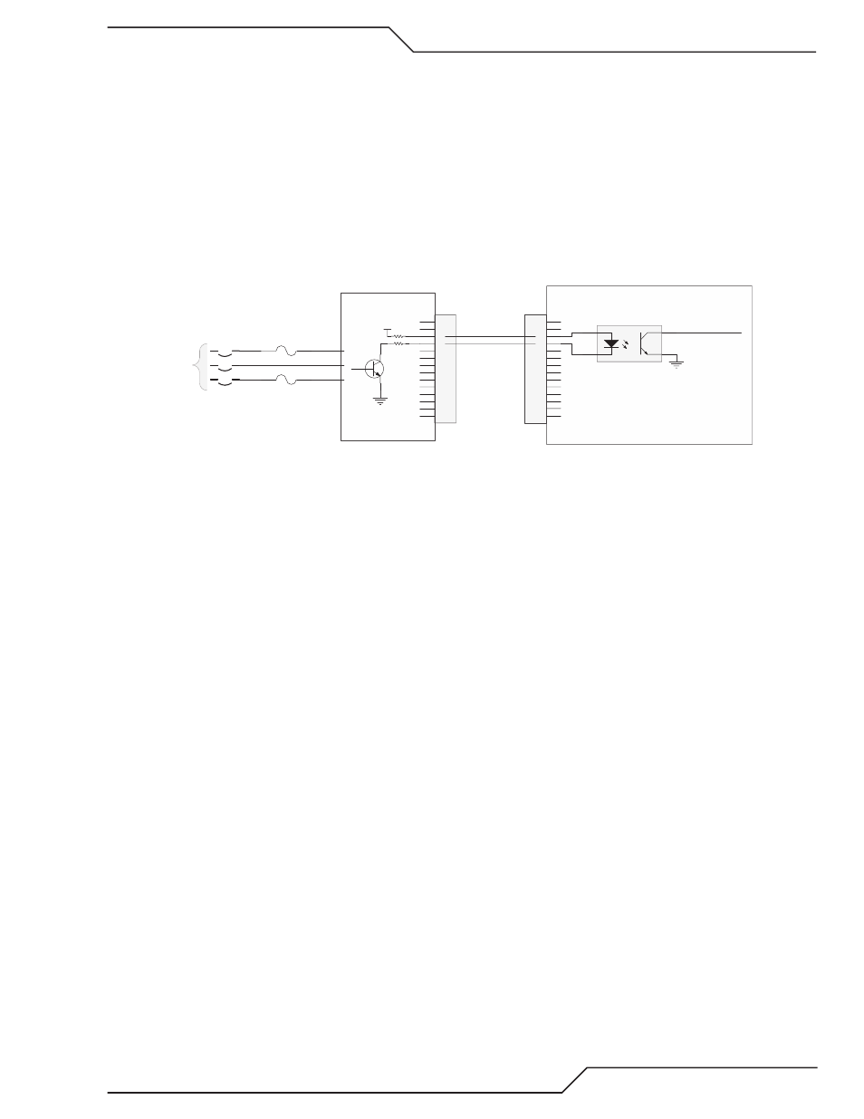
Missing AC Phase
The System Bias Supply board contains circuits to detect if one of the 3 C input phases is missing. long with
that it can also detect if the C voltage is too low or too high. Three phase voltage is supplied from the input
terminals through the ON/OFF Switch / circuit breaker CB1 to the System Bias board. The System Bias can
operate on any � of the 3 phases to supply control power and fault detection.
1
2
3
4
5
6
7
8
9
10
11
12
13
14
J62
1
2
3
4
5
6
7
8
9
10
11
12
13
14
J27
GND
+V
1
2
4
3
HCPL-817
U?
Missing Phase a
Missing Phase b
GND
To CPU PCB
J29-16
Missing Phase
I/O PCB
SYSTEM BIAS PCB
CB1
ON / OFF
F2
F1
J60-9,18
J60-5,14
J60-1,10
3 phase AC
Art # 12310
Normally when the phase is not missing the transistor is on which turns on the opto�isolator making the signal
“Missing Phase” low.
Causes for �01, missing phase code. Codes are displayed two different ways, with an “L” meaning “Latched”
or “Last”, before the number meaning it was a problem but isn’t right now or with an “E” meaning the problem
exists now.
L201 :
Most likely cause is an intermittent problem with the incoming power or possibly a loose connection on the
power cord at the back or the Ultra�Cut or uto�Cut plasma supply.
E201:
• Phase missing from the wall fuse box, blown fuse.
• F1 or F2, 8A 500V slow blow fuses blown.
• CB1 one phase open.
• System Bias board defective.
• I/O board defective.
Troubleshooting:
1. System Bias board has a red LED, D3, that lights if it detects a missing phase. If D3 is on, check J60 for all 3
phases.
a. If all 3 phases are not present at J60 check for incoming power, then the F1 & F� fuses. Finally the CB1.
b. If all 3 phases present and about equal voltage then change the System Bias board.
�. If D3, Missing Phase LED, is not on check for voltage at J�7�3 & � on the CCM. Normal voltage, with no
missing phase, at J�7 (or J6� on the System Bias board) pin 3 and pin �, relative to I/O PCB ground. (TP1)
should be between 10�1�VDC with pin 3 being a couple volts higher than pin �. If this is normal, problem
may be in the CCM.
3. If the voltage at J�7�3 & � is higher than 10�1�VDC and up to �0���VDC, make the same measurement at
J6� pin �. If still high there and you have confirmed all 3 phases are present at J60 then the System Bias is
defective.
�. If the voltage at J6��� is not high the wires between J�7 and J6� may be broken.