Section 3: installation, 1 common devices installation, Section 3: installation -1 – Tweco iCNC XT User Manual
Page 21: Common devices installation -1, Icnc xt
iCNC XT
Manual 0-5299
INSTALLATION
3-1
SECTION 3: INSTALLATION
3.1 Common Devices Installation
WARNINGS
DO NOT CONNECT the main power before all wiring is done and all cables are connected at both ends.
Always follow national wiring standard for wire sizes.
This section provides a basic wiring guide for limit switches, E-stops, Yaskawa drives, Down draft control and laser pointer. If you have a dif-
ferent type of setup and are unsure how to wire your machine please contact Victor Technologies for further support.
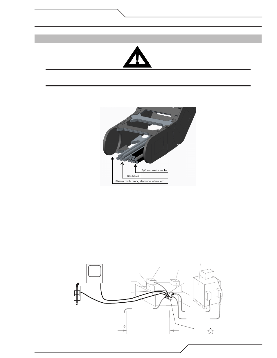
Grounding Requirements
Creating an Earth Ground
1. To create a solid, low resistance, earth ground, drive a 12 mm (1/2 in) or greater diameter copper clad ground rod at least 1.8 - 2.4m (6
- 8 ft) into the earth so that the rod contacts moist soil over most of its length. Depending on location, a greater depth may be required
to obtain a low resistance ground. Ground rods, typically 3m (10 ft) long, may be welded end to end for greater lengths. Locate the
rod as close as possible to the work table. Install a ground wire, 50mm² (1/0 AWG) or greater, between the ground rod and the star
ground point on the cutting table.
0 - 10 ft (0 - 3 m) Ideal
20 ft (6 m) Maximum
1/0
Ground Cable
Power Supply
‘Star’
Ground
Earth Ground
Rod
XT CNC
Controller
Lifter
Cutting Table
Cutting Machine / Gantry
Work Cable
Remote Arc
Starter
Star Ground on Cutting Table
Gas Control Module
Primary location
#4 AWG
Ground
(F)
Customer supplied
1/0
Ground Cable
(F1)
... . .. .
.. .. ..
Ground Cable