A.3 ihc lifter installation, Icnc xt – Tweco iCNC XT User Manual
Page 100
iCNC XT
A-2
APPENDIX
Manual 0-5299
A.2.3 Lifter Mounting Base
4.48 in.
(114 mm)
1.5 in.
(38 mm)
4 in. Stroke
12.45 in.
(316 mm)
8 in. Stroke
16.45 in.
(418 mm)
3.5 in.
(89 mm)
Height: 316/418mm [12.44/16.47in]
Width: 127mm [5.00in]
Depth: 100mm [3.93in]
• Dimensions are measurements without motor or other appliances.
• The base plate’s first mounting holes are 38mm from the bottom. All other mounting holes are distributed evenly after that
with 89mm spacing in accordance to the hole center line. Horizontally the distance between the holes is 114mm. Use M6
screws with the base plate.
• 8” stroke base plate is longer (418 mm instead of 316mm) and it has one more set of mounting holes on top for M6 screws
(again 89 mm up from the pair below).
• Torch holder is available for both 50mm and 35mm torch heads.
• Torch holder mounting surface is 100 mm out from the bottom of the Lifter base plate
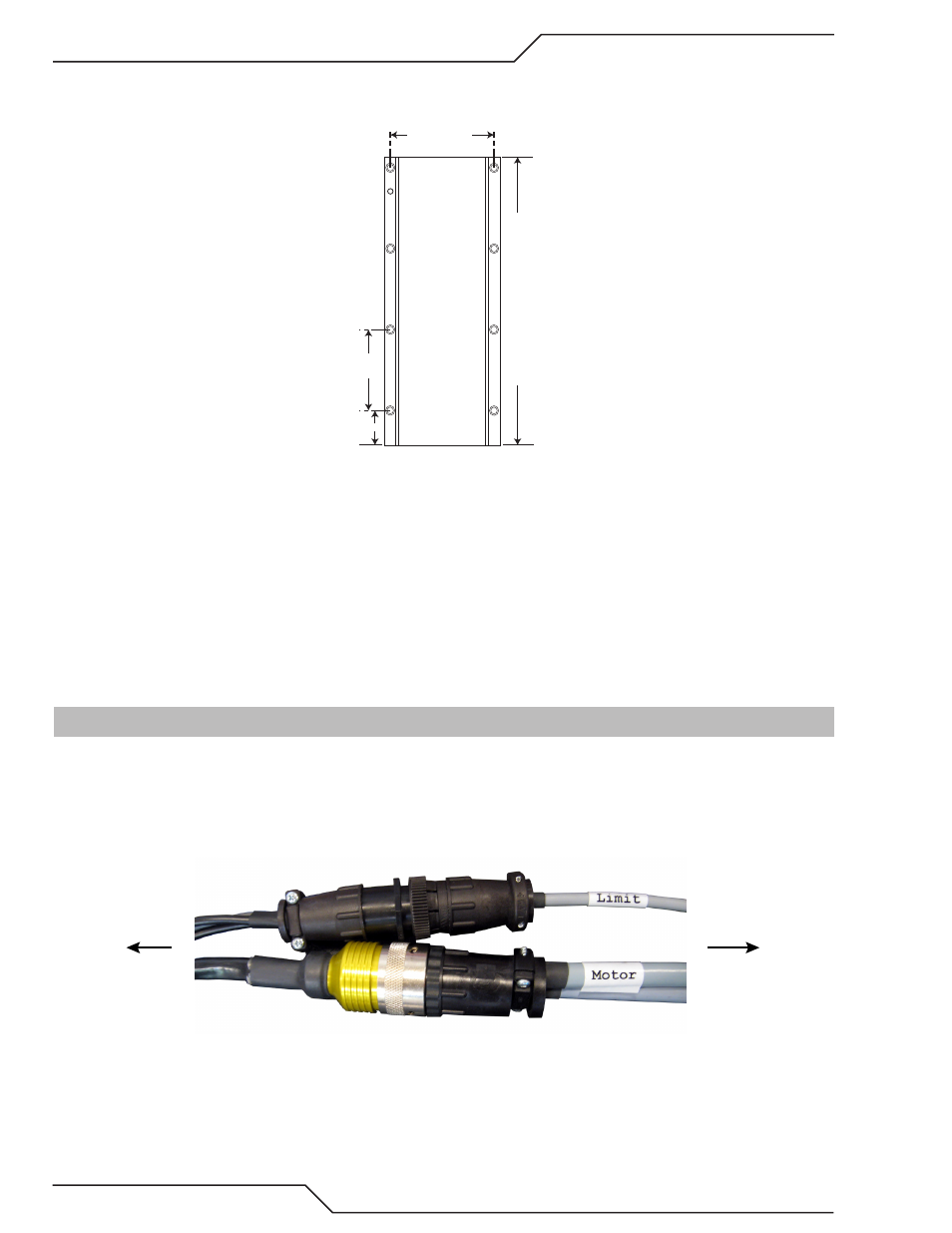
A.3 iHC Lifter Installation
1.Mount the lifter to a flat straight surface. Mounting hole placement in the mechanical drawings in section 2. Verify that the lifter is plumb
and true.
2. Connect the lifter motor cable, marked with a label motor, to the motor pig tail.
3. Connect the lifter limit cable, marked limits, to the 9pin male amp pig tail connector
Lifter
CNC
4. Route the cable to the cable track on the opposite side from plasma torch lead, ohmic and other high noise cables. See routing example
picture in section 2.
5. Connect the XT CNC end of the cable (37 pin CPC connector) to J104 connector at the back of the CNC.