05 primary power connections, Primary power connections -5 – Tweco 100 Auto-Cut User Manual
Page 41
Manual 0-4764
3-5 INSTALLATION
3.05 Primary Power Connections
The primary power cable must be supplied by the end user and connected to the power supply. Refer to local
and national electrical codes for suggested cable and fuse sizes.
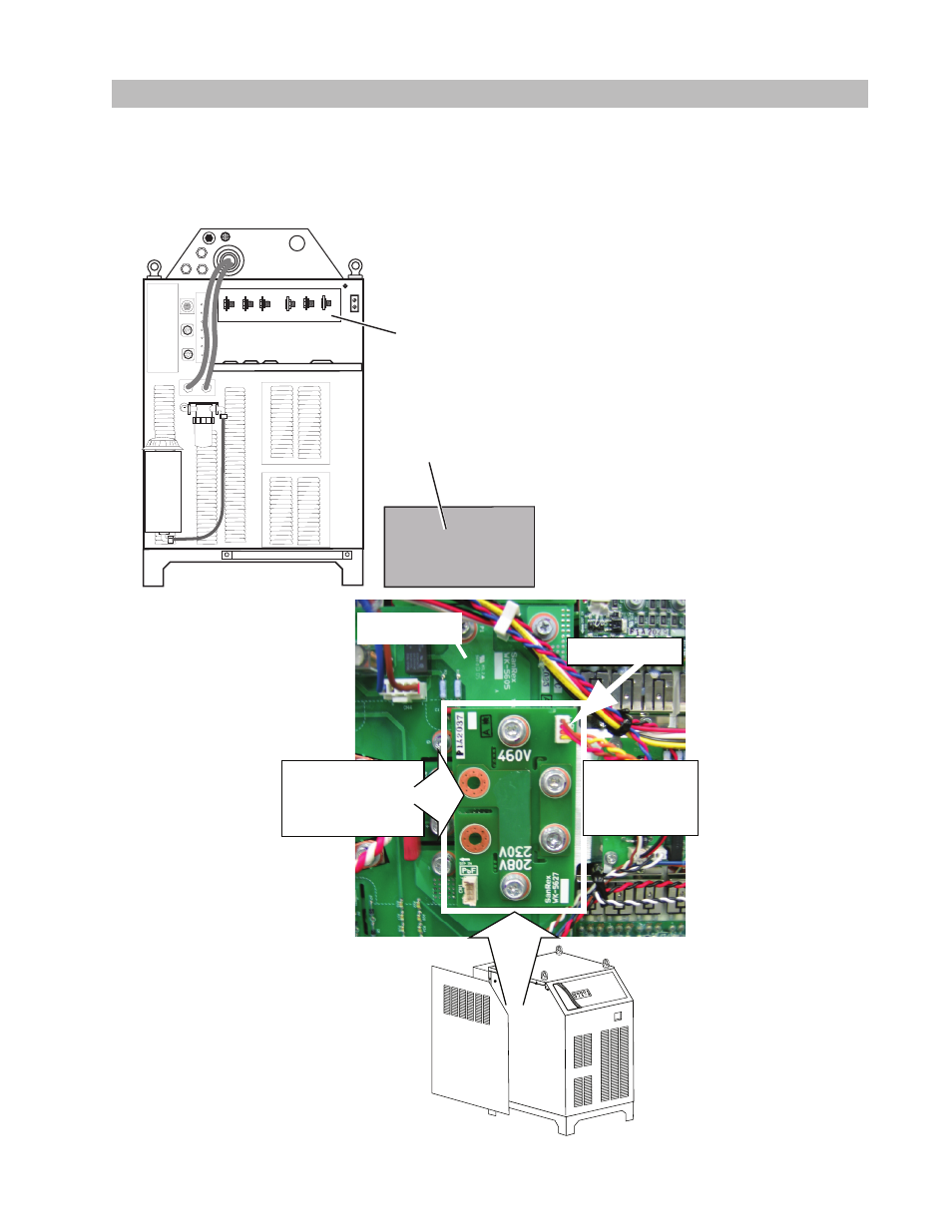
Remove the connections cover on the rear of the Power Supply. Use caution when removing the panel; there is
a ground wire connected to the inside of the panel. Do not disconnect this wire.
Connections Cover
(Removed)
Connection Panel
Art # A-04827
Check / Adjust Input Voltage Configuration
(208-230 / 460 V Only)
1. The power supply includes a voltage
configuration board which must be
positioned to match the primary input
voltage. Remove the power supply
left side panel and locate the voltage
configuration board. The input voltage
configuration is shown at the top of the
board.
2. If necessary, disconnect the jumper from
the top-right corner of the board, remove
the board and re-install with the correct
input voltage shown at the top of the
board. Reconnect the jumper to the top-
right corner of the board.
3. Re-install the power supply side panel.
Art # A-04856_AB
1. Unplug connector
2. Remove bolts.
3. Invert board.
4. Re-install board.
5. Plug in connector.
208/230V / 460V
Input Voltage Board
(Shown in 460V Position)
Inverter Module