Cutmaster 42 troubleshooting – Tweco 42 CutMaster Service Manual User Manual
Page 50
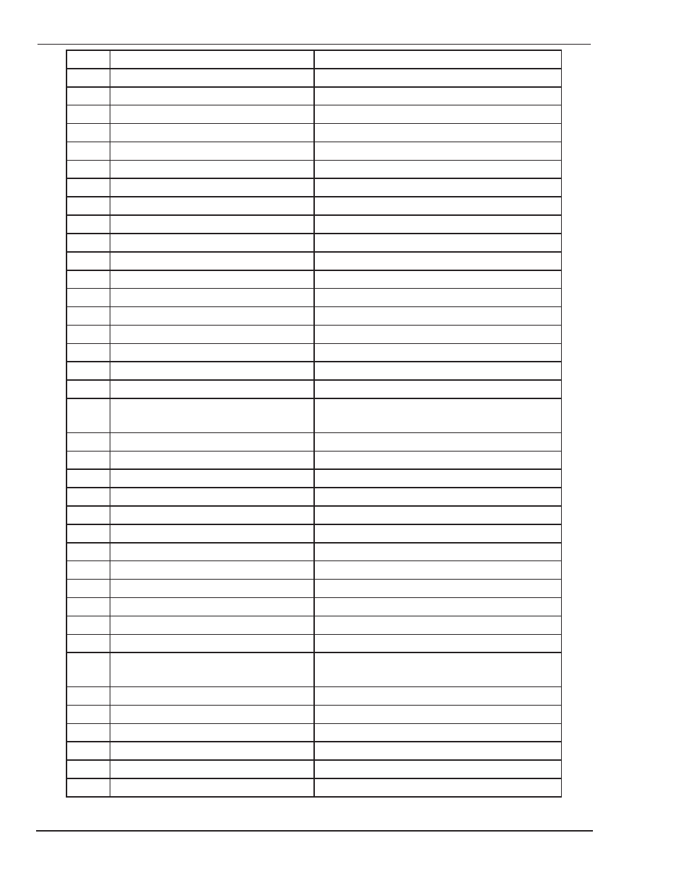
Troubleshooting 6-14 Manual 0-5171
CUTMASTER 42
TROUBLESHOOTING
J1
Pin function
signal
1
GND
0VDC
2
Control circuit power source
27VDC
3
Negative of solenoid control signal
0VDC (when soleniod is on)
4
Positive of solenoid control signal
27VDC
J2
1
Current control potentiometer
0 — 4VDC
2
N/A
N/A
3
Fault indicator signal
2VDC (when indication lights up)
4
N/A
N/A
5
Control circuit power supply
5VDC
6
GND
0VDC
7
Power indication signal
2VDC
8
N/A
N/A
9
Work indication signal
2VDC
10
Power indication signal
2VDC
J3
N/A
N/A
J4
1
Positive of TIP test signal
5VDC
2
TIP test signal
5VDC (when machine dose no work) 0VDC
the machine is woking
3
Control circuit power source
24VDC
4
GND
0VDC
5
Control circuit power source
-24VDC
J5
1
Drive circuit power
+15VDC
2
IGBT 1 pwm drive signal
15V p-p square wave
3
IGBT 2 pwm drive signal
15V p-p square wave
4
IGBT 2 pwm drive signal
15V p-p square wave
5
IGBT 1 pwm drive signal
15V p-p square wave
6
Overcurrent signal
>7VDC when over primary current protection
7
GND
0VDC
J6
1
Feedback of input voltage
41VDC(input 230vac)
23VDC(input 115vac)
2
GND
0VDC
J7
1
Power source of current sensor
15VDC
2
Power source of current sensor
-15VDC
3
Output current feedback
4
GND
0VDC