09 check main on / off switch, Cutmaster 42 troubleshooting – Tweco 42 CutMaster Service Manual User Manual
Page 44
Troubleshooting 6-8 Manual 0-5171
CUTMASTER 42
TROUBLESHOOTING
IGBT Testing
Multimeter Lead Placement
Diode Voltage
IGBT 1
Positive meter lead to test point 3
0.2000 to 0.8000 VDC
Negative meter lead to test point 2
IGBT 2
Positive meter lead to test point 5
0.2000 to 0.8000 VDC
Negative meter lead to test point 4
IGBT 3
Positive meter lead to test point 8
0.2000 to 0.8000 VDC
Negative meter lead to test point 7
VIGBT 4
Positive meter lead to test point 10
0.2000 to 0.8000 VDC
Negative meter lead to test point 9
PFC IGBT 1
Positive meter lead to test point 14
0.2000 to 0.8000 VDC
Negative meter lead to test point 13
PFC IGBT2
Positive meter lead to test point 12
0.2000 to 0.8000 VDC
Negative meter lead to test point 11
PILOT IGBT1
Positive meter lead to test point 26
0.2000 to 0.8000 VDC
Negative meter lead to test point 25
Table 6-2 IGBT’s, Multimeter set to measure Diode Voltage
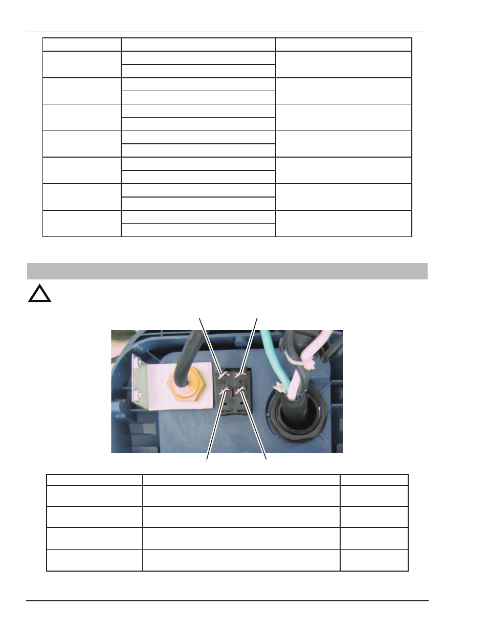
6.09 Check Main On / Off Switch
!
Read and follow safety information in Section 6.02 before proceeding.
Art # A-10245
1
2
3
4
Power Switch Testing
Multimeter Lead Placement
Impedance
Switch ON
Positive meter lead to testpoint 1
Negative meter lead to testpoint 2
0 to 1 Ω
Switch ON
Positive meter lead to testpoint 3
Negative meter lead to testpoint 4
0 to 1 Ω
Switch OFF
Positive meter lead to testpoint 1
Negative meter lead to testpoint 2
> 1k Ω
Switch OFF
Positive meter lead to testpoint 3
Negative meter lead to testpoint 4
> 1k Ω
Table 6-3 Power Switch, Multimeter set to measure ohms (Ω)