tekmar 422 Universal Reset Module User Manual
Page 23
23 of 32
© 2007
D 422 - 08/07
Variable Speed Injection
A standard wet rotor circulator can be connected to the
Variable Speed output on the control for Mix 1 and on
a Mixing Module for Mix 2. The control increases or
decreases the power output to the circulator when there
is a requirement for mixing. The circulator speed varies to
maintain the correct mixed supply water temperature at
the mix supply sensor. For correct sizing and piping of the
variable speed injection circulator, refer to essay E 021.
A visual indication of the current variable speed output is
displayed in the LCD in the form of a bar graph along with
the Mix 1 or the Mix 2 segment to indicate which mixing
device is being currently viewed.
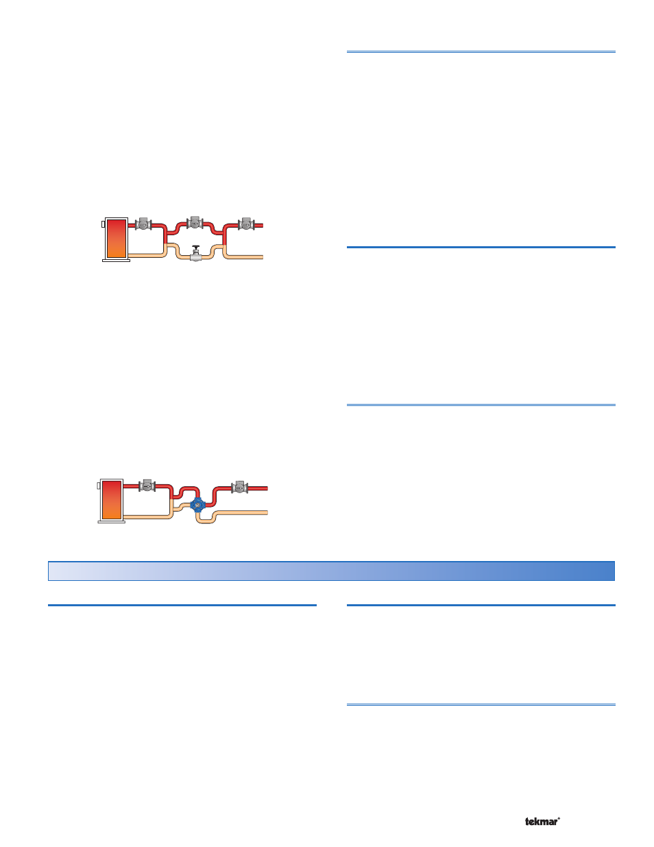
Floating Action
A floating action actuator motor can be connected to the
control (Mix 1) or a Mixing Module (Mix 2) on the Opn and
Cls terminals. The control pulses the actuator motor open
or close to maintain the correct supply water temperature
at the mix supply sensor when there is a requirement for
mixing. The mixing valve that the actuator is connected
to can be either a 2-way, 3-way or 4-way valve. A visual
indication as to whether the control is currently opening or
closing the mixing valve is displayed in the LCD with the
words OPN and CLS while viewing the Mix Supply or Mix
Target temperatures. Also, a visual indication of the current
position of the valve is displayed in the form of a bar graph
along with the Mix 1 or the Mix 2 segment to indicate which
mixing device is being currently viewed.
Mix 1 and Mix 2 Minimum
The Mix 1 and Mix 2 Minimum settings are the lowest
temperature that the control is allowed to use as a mix
target temperature. During mild conditions, if the control
calculates a mix target temperature that is below the mix
minimum setting, the mix target temperature is adjusted
to match the mix minimum setting. During this condition,
if the mixing supply temperature is near the mix minimum
setting, the Min segment turns on in the LCD when either
the mix target temperature or the mix supply temperature
is being viewed.
•
• Locate the Mix 1 and the Mix 2 Minimum settings in the
Adjust menu.
Mix 1 and Mix 2 Maximum
The Mix 1 Maximum and Mix 2 Maximum set the highest
water temperature that the control is allowed to use as a
mix target temperature. If the control does target the mix
maximum setting, and the mix supply temperature is near
the mix maximum temperature, the Max segment turns on
in the LCD when either the mix target temperature or the
mix supply temperature is viewed.
•
• Locate the Mix 1 and the Mix 2 Maximum settings in the
Adjust menu.
Boiler Minimum Protection
The control is capable of providing boiler protection from
cold mixing system return water temperatures. If the boiler
water temperature is cooler than the Boiler Minimum setting
while the boiler is firing, the control reduces the output from
the mixing devices. Both mixing outputs are reduced at the
same rate. Reducing the mixing output limits the amount of
cool return water to the boiler and allows the boiler water
temperature to recover. This feature can only be used if
the boiler sensor is on the supply or on the return but is not
available when the boiler sensor is not present.
Domestic Hot Water Temperature Operation
Section H
DHW Demand
A powered DHW Demand is required in order for the control
to provide heat to the DHW system. A DHW aquastat or
setpoint control is used as a switch in the DHW demand
circuit. The control registers a DHW Demand when a
voltage between 24 and 230 V (ac) is applied across the
DHW Demand terminals (53 and 54).
Once the control detects a DHW demand, the DHW Demand
segment turns on in the LCD.
Boiler Target Temperature
The boiler target temperature is at least as hot as the DHW
Exchange setting. The DHW demand overrides the boiler
reset target temperature, except when the boiler reset target
is higher than the DHW exchange setting.
•
• Locate the DHW Exchange setting in the Adjust menu.
DHW During UnOccupied
The control has a DHW Exchange UnOccupied setting that
allows the installer to select On or Off. When set to On, and
the control receives a DHW Demand during an UnOccupied
or Sleep period, the control continues operation of the DHW
system as it would during the Occupied and Wake periods.
When set to Off, the control can ignore a DHW Demand for
the duration of the UnOccupied and Sleep periods.