tekmar 422 Universal Reset Module User Manual
Page 21
21 of 32
© 2007
D 422 - 08/07
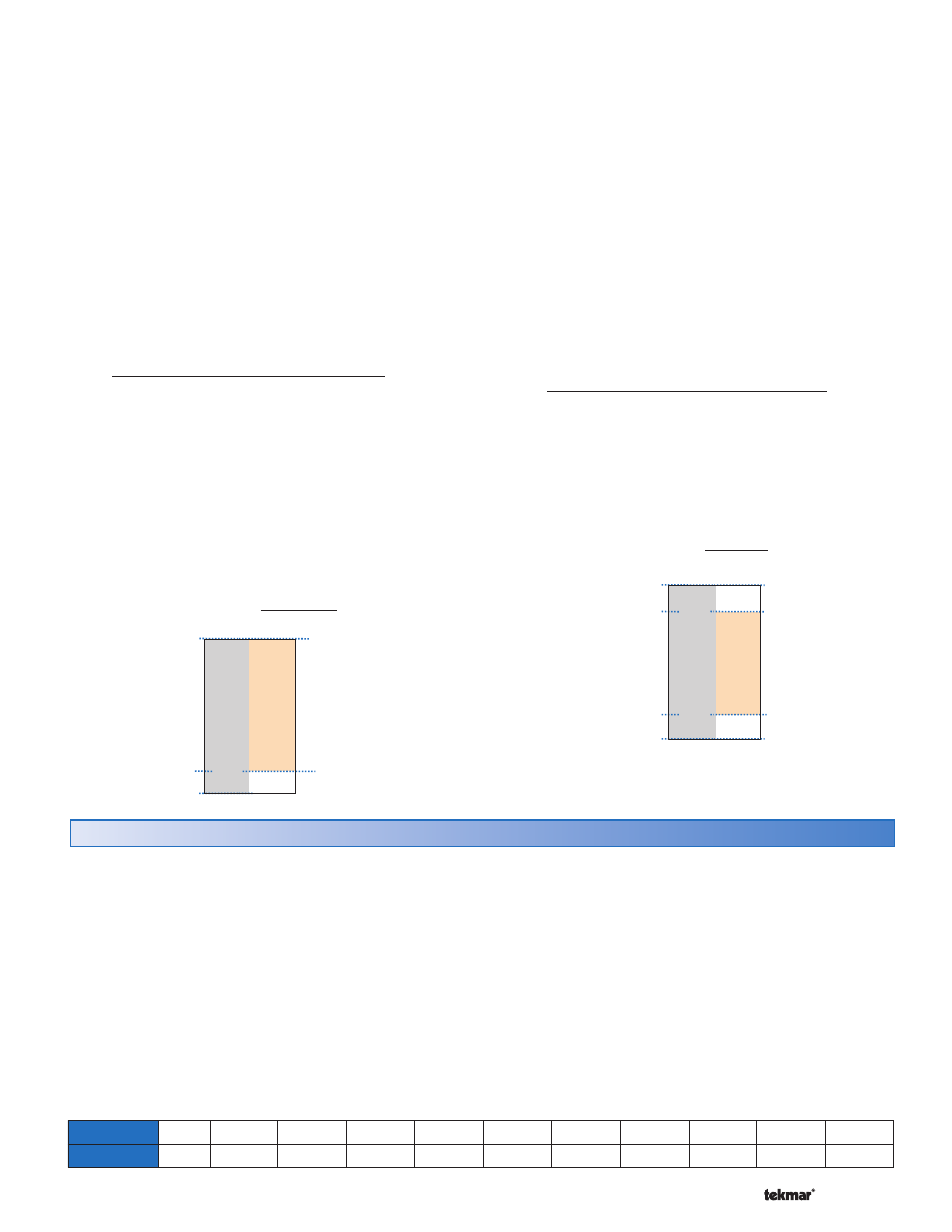
Minimum Modulation
The minimum modulation defines the minimum output
signal from the control to the boiler burner. It is based on
a percentage of the control’s output signal range.
The Minimum Modulation default setting is 0%.
For boilers with electronic operators, the boiler’s input signal
range may not match the output signal range of the 422
control. The Minimum Modulation setting limits the control
output range in order to match the boiler’s input range.
•
• Locate the Minimum Modulation setting in the Adjust
menu.
To calculate the Minimum Modulation, use the following
formula:
For 0-10 V (dc):
Minimum Modulation =
0 V (dc) - Boiler’s Minimum Input Signal x 100%
0-10
V
(dc)
Example:
A boiler requires a 1.8 V (dc) signal to fire the boiler at
low fire. The boiler can be modulated to 10 V (dc) where
it reaches high fire.
This means the boiler’s input signal range is 1.8 to
10 V (dc). The 422 control has an output signal range of
0-10 V (dc).
To make the two signal ranges the same, the Minimum
Modulation required is:
Minimum Modulation = 0 V-1.8 V x 100% = 18%
0
V-10
V
Maximum Modulation
The maximum modulation defines the maximum output
signal from the control to the boiler burner. It is based on
a percentage of the control’s output signal range.
The Maximum Modulation default setting is 100%.
For boilers with electronic operators, the boiler’s input signal
range may not match the output signal range of the 422
control. The Maximum Modulation setting limits the control
output range in order to match the boiler’s input range.
•
• Locate the Maximum Modulation setting in the Adjust
menu.
To calculate the Maximum Modulation, use the following
formula:
For 0-10 V (dc):
Maximum Modulation =
0 V (dc) – Boiler’s Maximum Input Signal x 100%
0-10
V
(dc)
Example:
A boiler’s input signal range is 2-9 V (dc). The 422 control
has an output signal range of 0-10 V (dc).
To make the two signal ranges the same, the Maximum
Modulation required is:
Maximum Modulation = 0 V-9 V x 100% = 90%
0
V-10
V
1.8 V (dc)
10 V (dc)
Control Rang
e
Boiler Rang
e
0 Vdc
18%
In some cases, multiple boilers may be required. In these
cases, the 422 allows for a connection to a tekmar Boiler
Control 264, 265, or 268. The 422 uses the modulating
output to provide a 0-10 V (dc) signal to the external input
terminals on the Boiler Control. The 422 controls the Boiler
Control target temperature by changing the voltage signal.
The Boiler Control responds to the boiler target by staging
the multiple boilers.
The following table can be used to convert a 0-10 V (dc)
signal to a boiler target temperature:
tekmar Stager Operation
Section D
To use the tekmar Staging operation, the following DIP
switch settings are required:
1.
Set the 422 Off / tekmar Stager DIP switch to tekmar
Stager.
2.
Set the 422 Boil Sup / Ret DIP switch to Sup.
3.
Set the 422 Boil On-Off / Mod DIP switch to Mod.
The 422 boiler sensor must be located on the supply pipe
leading from the boilers. On the Boiler Control 264, 265,
or 268, the External Input / Stand Alone DIP switch must
be set to External Input. Any domestic hot water (DHW)
demands or setpoint demands in the system must connect
to the 422 in order to allow for DHW or setpoint priority.
10 V (dc)
Control
Rang
e
Boiler
Rang
e
0 Vdc
0 V (dc)
2.0 V (dc)
20%
90%
Voltage (dc)
0
1
2
3
4
5
6
7
8
9
10
Boiler Target
Off
50°F
(10°C)
68°F
(20°C)
86°F
(30°C)
103°F
(40°C)
121°F
(50°C)
139°F
(60°C)
157°F
(70°C)
174°F
(80°C)
192°F
(90°C)
210°F
(99°C)