tekmar 263 Boiler Control User Manual
Page 8
©
2009 D
263
-
03/09
8
of
36
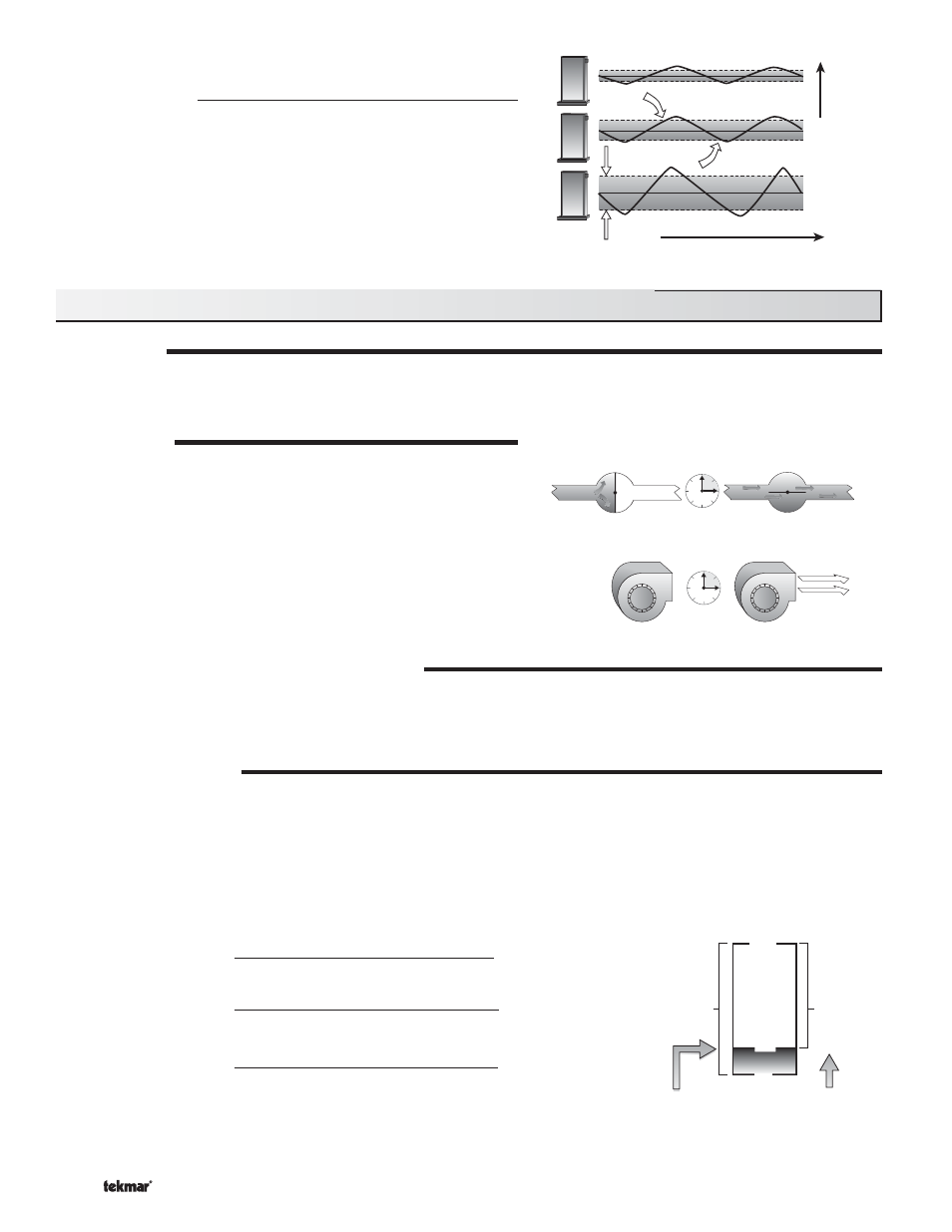
Auto Differential
If the Auto Differential is selected, the control automatically determines
the best differential as the load changes. This reduces potential short
cycling during light load conditions.
Increasing Load
Time
Differential
On
Off
MODULATION
When operating in Mode 2, the control provides a modulating output signal to operate a single modulating boiler. The control first
closes the boiler contact on to ignite the ignition sequence. The boiler is then modulated from the minimum modulation using
Proportional, Integral and Derivative (PID) logic in order to satisfy the boiler target temperature.
MOTOR SPEED
The Motor Speed is the amount of time the boiler requires to go from 0%
modulation to 100% modulation.
Gas valve actuating motors have a design time from fully closed to
fully open which can be found in the manufacturer’s manual. The
Motor Speed
should be set to this time.
The Motor Speed setting for a Variable Frequency Drive (VFD) is the
amount of time required to go from a stopped position to 100% fan
speed. Since a VFD has a very quick response rate, it may be necessary
to increase the Motor Speed setting in order to increase the stability of
the boiler modulation.
MODULATION RANGE (4 to 20 mA or 0 to 20 mA)
The modulation output (Mod 1) can be adjusted from a 4 to 20 mA output range or to a 0 to 20 mA output range using the
Boil Modulation
setting. The resulting modulation output signal can be converted to a 0 to 5 V (dc), 1 to 5 V (dc), 0 to 10 V (dc), and
2 to 10 V (dc) output using external resistors. The modulation output signal can be converted to a 0 to 135 Ω (W R B) output using
a 0 to 135 Ω Converter 005. Refer to the Modulation Output section in Step 4 of the Installation section.
MINIMUM MODULATION
The minimum modulation defines the minimum output signal from the control to the boiler burner. It is based on a percentage of
the control’s output signal range.
The Minimum Modulation setting for boilers with power burners is typically set to 0%.
For boilers with electronic operators, the boiler’s input signal range may not match the output signal range of the 263 control. The
Minimum Modulation
setting limits the control output range in order to match the boiler’s input range.
To calculate the Minimum Modulation, use the following formulae:
For 4 to 20 mA:
Minimum Modulation =
4 mA – Boiler’s Minimum Input Signal
4 - 20 mA
x 100%
For 0 to 10 V (dc):
Minimum Modulation =
0 V (dc) – Boiler’s Minimum Input Signal
0 – 10 V (dc)
x 100%
For 2 to 10 V (dc):
Minimum Modulation =
2 V (dc) – Boiler’s Minimum Input Signal
2 – 10 V (dc)
x 100%
Section B3: Mode 2 - One Modulating Boiler and Pump Operation
MINIMUM MODULATION
18%
0%
0 V (dc)
1.8 V (dc)
100%
10 V (dc)
10 V (dc)
Control's
Output
Signal
Range
Minimum
Modulation
Boiler's Minimum
Input Signal
Boiler's
Input
Signal
Range