Definitions – tekmar 263 Boiler Control User Manual
Page 4
©
2009 D
263
-
03/09
4
of
36
Section A
General
Operation
Page 4 - 5
Section B
Boiler
Operation
Page 6 - 10
Section C
Pump
Operation
Page 11
Sequence of Operation
Section A: General Operation
The following defined terms and symbols are used throughout this manual to bring attention to the presence of hazards of various risk
levels, or to important information concerning the life of the product.
- Warning Symbol: Indicates presence of hazards which can cause severe personal injury, death or
substantial property damage if ignored.
- Double insulated
- Local level, appliances
INSTALLATION
CATEGORY II
Definitions
Section D
Boiler Reset
Operation
Page 12 - 14
Section E
DHW
Operation
Page 15 - 17
Section F
Setpoint
Operation
Page 17 - 18
POWERING UP THE CONTROL
When the control is powered up, all segments in the LCD are turned on for 2 seconds. Next, the control displays the control type
number in the LCD for 2 seconds. Next, the software version is displayed for 2 seconds. Finally, the control enters into the normal
operating mode.
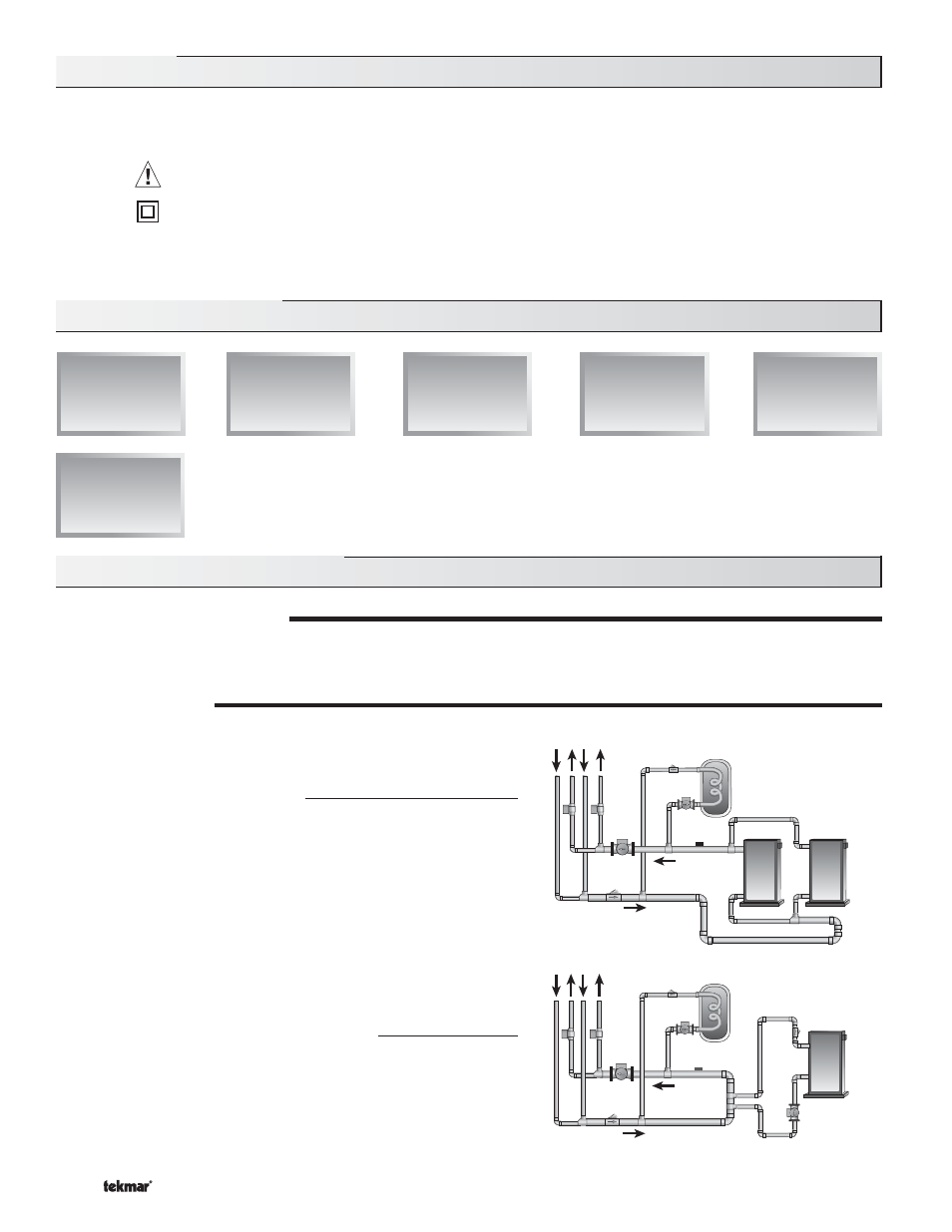
OPERATING MODES
The control operates in two different operating modes:
Mode 1 – Two ON / OFF Stages
Mode 1 operates up to two on / off boilers or one boiler with two stages.
Mode 2 – One Modulating Boiler & Pump
Mode 2 operates one modulating boiler and the boiler pump.
Boiler
Sensor
Primary
Pump
DHW
Pump
Primary
Pump
Boiler
Sensor
Boiler
Pump
DHW
Pump