tekmar 263 Boiler Control User Manual
Page 23
23 of 36
© 2009 D 263 - 03/09
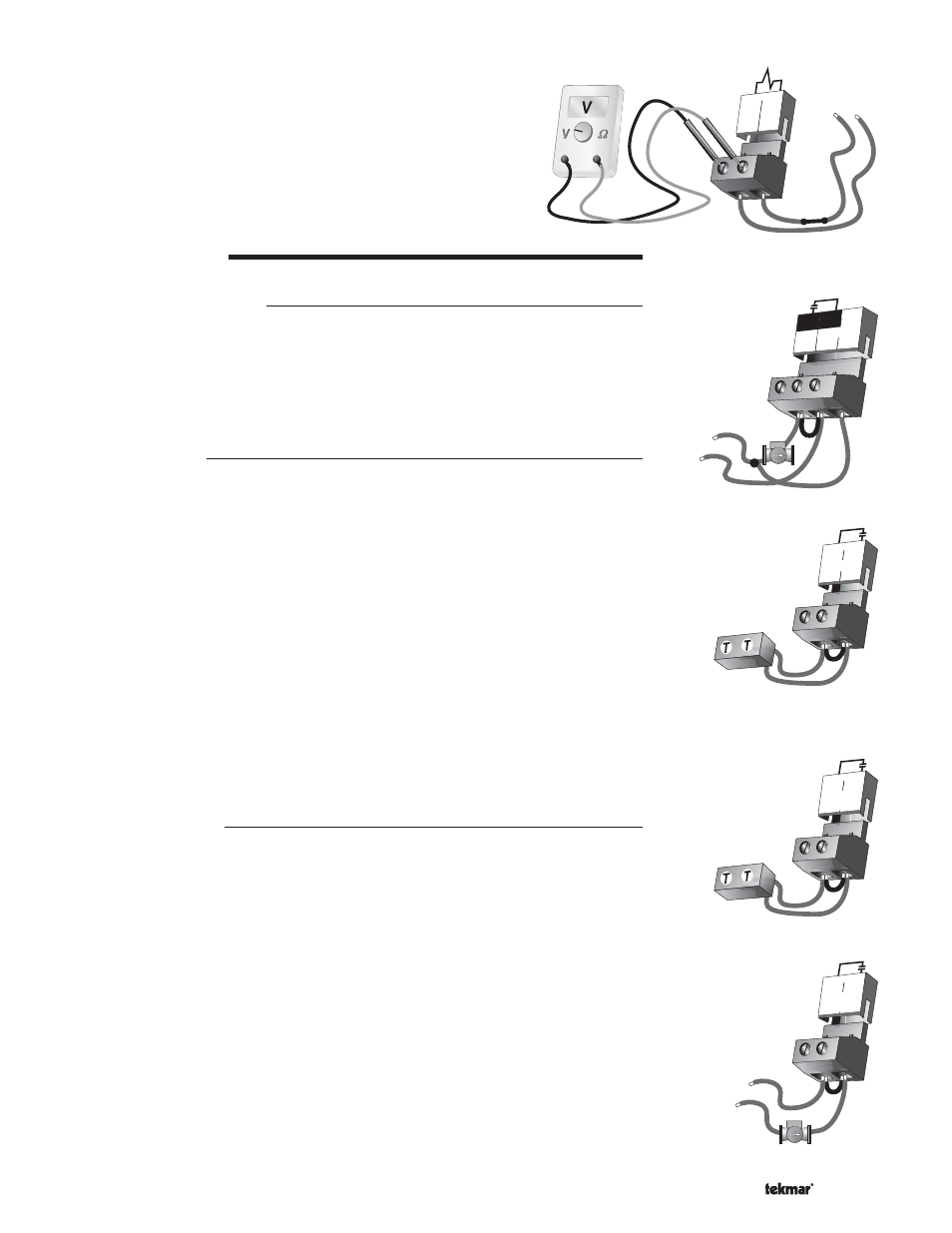
Setpoint Demand
If a setpoint demand is used, measure the voltage between the
Setp Dem
and the Com Dem terminals (5 and 4). When the setpoint
demand device calls for heat, between 20 and 260 V (ac) should be
measured at the terminals. When the setpoint demand device is off,
less than 5 V (ac) should be measured.
TEST THE OUTPUTS
Primary Pump (Prim P1)
If a primary pump is connected to the Prim P1 terminal (6), make sure that power to the
terminal block is off and install a jumper between the Power L and Prim P1 terminals
(7 and 6). When power is applied to the Power L and Power N terminals (7 and 8), the
primary pump should start. If the pump does not turn on, check the wiring between the
terminal block and pump and refer to any installation or troubleshooting information
supplied with the pump. If the pump operates properly, disconnect the power and
remove the jumper.
Relay 1 Contact
Mode 1 - Two ON / OFF Stages
If an on / off boiler or a Lo fire boiler stage is connected to the Relay 1 terminals
(11 and 12), make sure power to the boiler circuit is off, and install a jumper between
the terminals. When the boiler circuit is powered up, the boiler should fire. If the boiler
does not turn on, refer to any installation or troubleshooting information supplied with
the boiler. (The boiler may have a flow switch that prevents firing until the primary pump
(Prim P1) or boiler pump (P2) is running). If the boiler operates properly, disconnect the
power and remove the jumper.
Mode 2 - One Modulating Boiler and Pump
If a modulating boiler is connected to the Relay 1 terminals (11 and 12), make sure
power to the boiler circuit is off, and install a jumper between the terminals. When the
boiler circuit is powered up, the boiler should ignite and operate at Lo fire. The boiler
may require a modulating signal before firing. If the boiler does not turn on, refer to any
installation or troubleshooting information supplied with the boiler. (The boiler may
have a flow switch that prevents firing until the primary pump (Prim P1) or boiler pump
(P2) is running). If the boiler operates properly, disconnect the power and remove the
jumper.
Relay / P2 Contact
Mode 1 - Two ON / OFF Stages
If an on / off boiler is connected to the Relay 2 / P2 terminals (13 and 14), make sure
power to the boiler circuit is off, and install a jumper between the terminals. When
the boiler circuit is powered up, the boiler should fire. If the boiler does not turn on,
refer to any installation or troubleshooting information supplied with the boiler. (The
boiler may have a flow switch that prevents firing until the primary pump (Prim P1) or
boiler pump (P2) is running). If the boiler operates properly, disconnect the power and
remove the jumper.
To test the second stage of a two stage boiler, the Lo fire must firing before the Hi fire
will operate. Once the Lo stage is firing, test the Hi fire stage in the same way as an
on / off boiler.
Mode 2 - One Modulating Boiler and Pump
If a boiler pump is connected to the Relay 2 / P2 terminals (13 and 14), make sure that
power to the terminal block is off and install a jumper between the terminals. When
power is applied to circuit, the boiler pump should start. If the pump does not turn on,
check the wiring between the terminal block and pump and refer to any installation or
troubleshooting information supplied with the pump. If the pump operates properly,
disconnect the power and remove the jumper.
20 to 260 V (ac)
5
4
Com
Dem
Setp
Dem
88
Power
N
L
Prim
P1
6 7
L
N
115 V (ac)
14
13
Relay
2 / P2
L
N
115 V (ac)
12
11
Relay
1
1
14
13
Relay
2 / P2