Powers SH1430 2 Valve HiLo & DV User Manual
Technical instructions
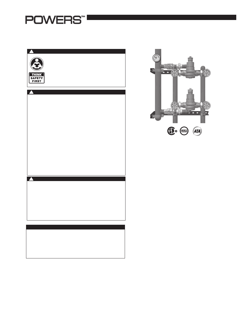
HydroGuard
®
XP Series LFSH1430
2 Valve Hi/Lo
Technical Instructions
IS-P-SF-SH1430-2V-HiLo
Advanced Thermal Activation
Description
n
Powers' HydroGuard
®
XP Series LFSH1430 Hi/Lo systems are
fully assembled factory tested systems, designed to provide
safe water throughout commercial and institutional facilities.
HydroGuard
®
XP Series LFSH1430 Hi/Lo systems consist of
LFMM430 and Series LFSH1430 thermostatic valves which
utilize paraffin-based actuation technology to sense and adjust
outlet temperature.
Each system includes ball valves, pressure/temperature
gauges and Powers' triple-duty checkstops. Hi/Lo systems also
include a PRV. Optional equipment include cabinets.
Operation
n
Two-valve supply fixtures feature a low capacity valve that
works in parallel with a high capacity valve. During low
demand, the low capacity valve handles the load requirements.
As the load demand is increased, the pressure reducing valve,
which is set at a certain pressure differential, will open and
allow flow through the high capacity valve to assist the low
capacity valve in meeting the increased load requirements.
WARNING
!
Read this Manual BEFORE using this equipment.
Failure to read and follow all safety and use infor-
mation can result in death, serious personal injury,
property damage, or damage to the equipment.
Keep this Manual for future reference.
You are required to consult the local building and plumb-
ing codes prior to installation. If the information in this
manual is not consistent with local building or plumbing
codes, the local codes should be followed. Inquire with
governing authorities for additional local requirements.
WARNING
WARNING
!
Need for Periodic Inspection and Yearly Maintenance:
Periodic inspection and yearly maintenance by a licensed con-
tractor is required. Corrosive water conditions and/or unauthor-
ized adjustments or repair could render the valve ineffective for
service intended. Regular checking and cleaning of the valve’s
internal components and check stops helps assure maximum
life and proper product function. Frequency of cleaning and
inspection depends upon local water conditions.
FAILURE TO COMPLY WITH PROPER INSTALLATION AND
MAINTENANCE INSTRUCTIONS COULD CONTRIBUTE TO THE
VALVE FAILURE.
This Hot Water Master Tempering Valves cannot be used for
tempering water temperature at fixtures. Severe bodily injury
(i.e., scalding or chilling) and/or death may result depending
upon system water pressure changes and/or supply water
temperature changes. ASSE standard 1016, 1069 or 1070 listed
devices should be used at fixtures to prevent possible injury.
These Hot Water Tempering Valves are designed to be
installed at or near the boiler or water heater. They are not
designed to compensate for system pressure fluctuations and
should not be used where ASSE standard 1016, 1069 or 1070
devices are required. These valves should never be used to
provide “anti-scald” or “anti-chill” service.
The components of the system must be of materials with a
construction capable of withstanding the high limit output tem-
peratures of the water heating source.
WARNING
!