Warning, Repair kit, Troubleshooting – Powers LM495 Series Thermostatic Tempering Valves for Individual Lavatory Installations User Manual
Page 2: Warranty, Quick-connect installation, Notice
To Adjust Temperature (Figure 3)
n
1. Let the water flow for at least two minutes to allow supply tem-
perature to stabilize.
2. Place a thermometer in the outlet water stream.
3. Loosen handle screw with hex wrench.
4. Handle must be lifted
1
⁄
4
” to adjust temperature. Rotate handle
clockwise to decrease temperature and counter-clockwise to
increase the temperature.
5. Lower handle and tighten screw.
6. Check for outlet temperature.
Pressure Differential between Hot & Cold Water Supplies must be
less then 25%.
It is recommended that shutoff valve(s) be installed on the inlet(s) to
facilitate service of the LFLM495 valve.
Repair Kit
n
Troubleshooting
n
Fluctuating or erratic hot water temperature at fixture:
Unbalanced pressure. Install balancing or throttling valve at the hot and
cold water supplies and adjust accordingly for demand.
Hot water backing up into cold water line:
Hot water pressure is higher than cold water pressure.
Examine check valves for dirt & debris, clean as necessary.
Cannot adjust water temperature to desired temperature:
Install balancing or throttling valve at the hot and cold water supplies
and adjust accordingly for demand.
High pressure drop through the tempering valve:
Valve undersized. Install larger thermostatic tempering valve.
Insufficient hot water during peak demand:
Check flow requirement during peak demand period. Use larger
thermostatic tempering valve.
Turn
Hotter
Hex Wrench
Colder
Unscrew, Lift Cap
to Adjust
Figure 3.
Model
Part #
Description
LFLM495
495 100
Plunger/Motor Assembly
Warranty
n
The Seller warrants that the equipment manufactured by it and covered by this order or contract is free from defects in material and workmanship and, without
charge, equipment found to be defective in material or workmanship will be repaired, or at Seller’s option replaced F.O.B. original point of shipment, if written
notice of failure is received by Seller within one (1) year after date of shipment (unless specifically noted elsewhere), provided said equipment has been properly
installed, operated in accordance with the Seller’s instructions, and provided such defects are not due to abuse or decomposition by chemical or galvanic action.
THiS ExprESS wArrAnTy iS in liEu OF And ExcludES All OTHEr wArrAnTiES, guArAnTEES, Or rEprESEnTATiOnS, ExprESS OF impliEd. THErE ArE
nO impliEd wArrAnTiES OF mErcHAnTABiliTy Or OF FiTnESS FOr A pArTiculAr purpOSE. The Seller assumes no responsibility for repairs made on the
Seller’s equipment unless done by the Seller’s authorized personnel, or by written authority from the Seller. The Seller makes no guarantee with respect to material
not manufactured by it.
WARNING: This product contains chemicals known to the
State of California to cause cancer and birth defects or
other reproductive harm.
For more information: www.watts.com/prop65
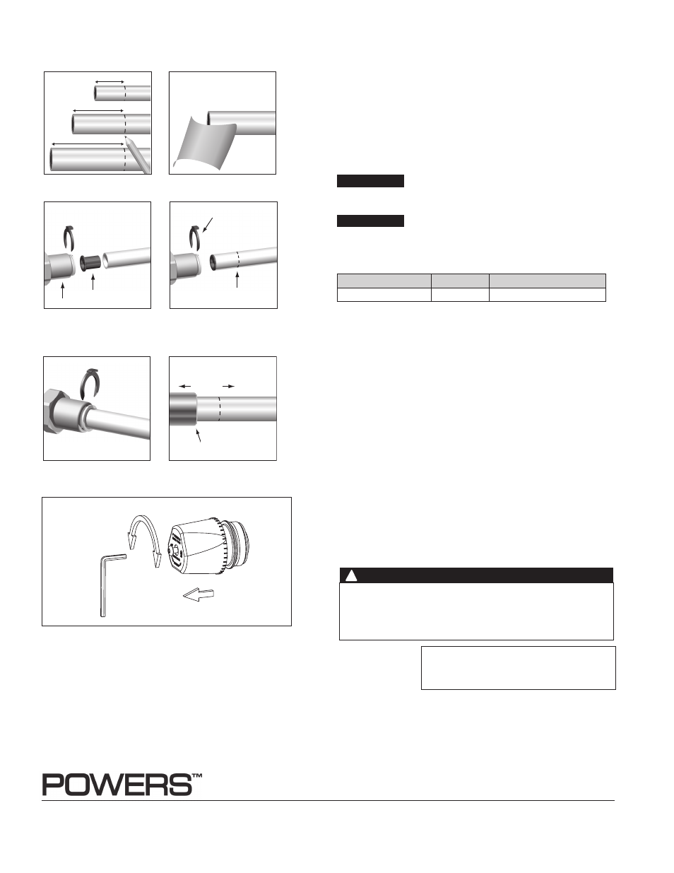
1. Mark pipe as shown.
This is pipe insertion depth.
2. Clean pipe end.
1. Remove collet clip.
2. Depress collet.
3. Pull tubing from tailpiece.
3. If using PEX tubing, insert pipe
stiffener (provided) into end of
pipe.
4. Push tubing into tailpiece up to
mark.
5. Insert collet clip.
To Connect
To Disconnect
PEX tubing only
Pipe Stiffener
Tail Piece
Mark
Collet clip
Collet depressed
1
1
⁄
2
in. (38.1mm)
1
3
⁄
4
in. (44.45mm)
1
7
⁄
8
in. (47.63mm)
1
⁄
2
in.Pipe (12.7mm)
3
⁄
4
in.Pipe (19.05mm)
1 in.Pipe (25.4mm)
Quick-Connect Installation
n
NOTICE
NOTICE
WARNING
!
For valves with CPVC or PEX end connections, do not exceed
the tubing manufacturers pressure and temperature ratings.
Refer to the tubing manufacturers product specifications for that
information.
USA: Tel: (800) 669-5430 • Fax: (847) 229-0526 • powerscontrols.com
Canada: Tel: (905) 332-4090 • Fax: (905) 332-7068
•
powerscontrols.ca
Latin America:
Tel: (52) 81-1001-8600 • powerscontrols.com
IS-P-LM495 1427
EDP# 6511208
© 2014 Powers
A Watts Water Technologies Company