Installation instructions (cont.), Preventative maintenance, Safety guidelines – Powers 720 Series VisuGuard T/P Combination Tempering Valve with LCD Temperature Display User Manual
Page 3
Installation Instructions (Cont.)
n
3
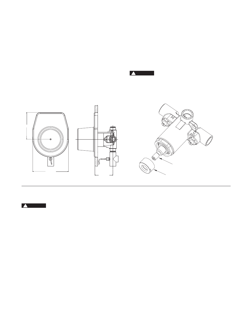
HIGH TEMP. STOP
STEM
Figure 5
1-5/8 ±.25"
5 [127]
3-3/4 [95]
vis-ewb-front-and-side-with-rough-in-guide
Figure 4
3 3/4 (95)
5 (127)
1 5/8 (25)
Thermistor Assembly
7. Locate and insert the thermistor (temperature probe) into the sup-
plied compression outlet. See Figure 3 for the probe depth. Improper
installation of depth probe can result in imprecise temperature read-
ings. Firmly tighten to prevent leakage. Do not hang trim plate on
wall using temperature probe wire as this could cause damage to
probe. Pressurize and test the system to verify zero leakage.
8. When piping installation is completed and before doing the finished
wall, slide rough-in guide on to the valve stem and press fit into place
(Figure 4). The rough-in guide will ensure the proper size opening for
valve, shutting off checkstops and and repair accessibility.
9. Attach indicator gasket to the back of the trim plate making sure
diagonal holes on the gasket matches diagonal holes on the trim
plate and locator hole matches the top hole on the trim plate. Peel
off backing of the trim plate gasket and attach to the inside top edge
of the trim plate.
10. Install trim plate.
11. Maximum Temperature Setting
Maximum temperature setting adjustment (see Figure 5) must be set
on the job and in no case it should be greater than 110°F (43°C). The
high temperature limit stop is located on the bonnet. Rotate handle
to the maximum desired outlet temperature. With an open-end
wrench, screw high temperature limit stop into the bonnet until it
touches stem's shoulder. Close valve and open it to full hot position
to verify setting.
12. Snap on the indicator plate. Guide on the back of the plate goes into
the locator hole.
13. Install sleeve O-ring on the bonnet. Slide sleeve on the bonnet.
Indicator plate must be installed before sleeve.
14. Install handle and tighten the setscrew.
CAUTION
!
Preventative Maintenance
n
Before servicing checkstops, always turn off the upstream water sup-
ply. When servicing valve, turn off water supply upstream or close the
checkstops.
Every Three Months:
1. Check the maximum temperature setting. Refer to Step 11 of instal-
lation instruction section.
Every Twelve Months
1. Open up the checkstops and check for the free movement of the
poppet. To access the checkstop, remove the handle and trim
plate.
2. Remove the valve bonnet and rinse all grit and impurities from the
cartridge.
Winterize valves that are used outdoors. Remove and store the internal
components and drain all water from the valve.
Safety Guidelines
n
Adherence to these guidelines and recommendations promotes safe
product use and ensures proper valve performance.
1. Thermostatic valves are control devices which must be cleaned
and maintained on a regular basis. Powers specifies periodic main-
tenance at least once a year or immediately after any changes are
made to the plumbing system. Annual cleaning is recommended,
however, frequency of cleaning depends on quality of local water
conditions.
2. The high temperature limit stop setting must be adjusted to limit the
distance the user can rotate the handle towards the full hot water
position.
WARNING
!