Powers 595 Series 11 Self-Operating Temperature Regulators - Type DB & DS Double Seat, Balanced User Manual
Page 9
Testing The Thermal System
■
If the valve is not responding to temperature change,
test the thermal system.
1. Stop the flow of fluid through the line.
2. DA: Raise the temperature of the bulb above the set point
temperature by placing it in a container of hot water. This
will cause the plug to fully seat.
RA: Raise the temperature of the bulb above the set point
temperature by placing it in a container of hot water.
This will cause the plug to fully open.
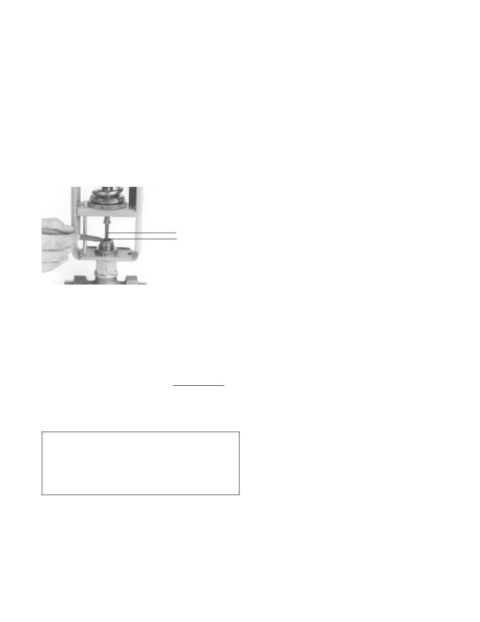
3. Figure 15. With the valve plug in the desired position, use
a felt tip pen to mark the position of the packing gland
assembly on the stem.
4. DA: Place the bulb in a pan of cool water. Cool the bulb 30°F
(16°C) below set point so the valve is fully open.
RA: Place the bulb in a pan of cool water. Cool the bulb to or
beyond the set point so the valve plug is seated.
5. Use the pen to mark the new position of the packing gland
assembly on the stem.
6. The distance between the marks is the valve plug travel.
This should correspond with the TRAVEL value in the VALVE
DIMENSIONS table on page 14. No movement or only partial
movement indicates the thermal system is defective and
should be replaced with a new system.
WARNING:
Failure of the #11's thermal system will cause a heat-
ing valve to full open and a cooling valve to full close.
If either of these valve states results in an unsafe process
condition, a high-limit shutdown device, such as a Powers
AquaSentry, should be used.
15. Valve travel
Distance between two
marks = Valve Travel
9