Installation, Figure 4 – Powers 450-900 HydroPanel II Shower System with Biltmore 900 Pressure Balancing Valve User Manual
Page 2
TI450-900
Page 2
Before installation of any Hydropanel II unit, rotate the stem (or
handle if attached) of the valve to its full clockwise position (OFF).
POSITION THE HYDROPANEL II UNIT
(See Figures 1 and 2) Determine the horizontal position of the unit
according to shower room layout, and mark the centerline.
For multiple shower applications, the recommended minimum
distance between the centerline of two units is 36
"
[1914mm].
1. Determine the floor-to-showerhead height for the unit.
Recommended heights are listed below:
Men - 77
"
[1956mm]
Youth - 66
"
[1676mm]
Women - 70
"
[1778mm]
Youth - 60
"
[1524mm]
2. The preassembled copper tubing supply water inlets are
4-1/8
"
[105 mm] from the top of the shroud, and 3-5/16
"
[84mm] left and right of the centerline. Adjust supply
piping accordingly.
Install the Piping Assembly
The valve handle assembly, piping and Hydropanel II shrouding
must be separated before mounting to wall. For #4504004 and
#4504005 Hydropanel II units, the handshower, hose and show-
erhead base come preassembled to the shrouding. Refer to
Figure 4.
3. Detach the valve assembly by removing valve retaining
screw, handle and collar. Undo the screws at D and D
'
and
take off the dial insert.
4. Remove the screw at A above the showerhead. Slide the
piping out of the shrouding; the shower head remains
attached to the shroud.
5. For mounting the piping assembly upper bracket (B), use
the bracket as a template and drill two small holes in the wall
at showerhead height.
6. For mounting the piping assembly lower bracket (C), drill one
small holes in the wall 23-1/2
"
[587mm] below the shower-
head on the centerline.
7. Install any mounting anchors as detailed by the individual
room specifications.
8. Secure upper piping bracket B with mounting screws
(not included).
9. Secure lower piping bracket C with mounting screw (not
included).
10. Connect the supply lines to the piping assembly.
Attach the Shrouding
Do Not remove the entire chrome plated end cap from the
shrouding; it functions as an end cap and gasket for shroud
extension. Part of the end cap can be broken out to provide verti-
cal and horizontal piping clearance.
10. To remove scored section, hit it sharply with a hammer.
11. To connect the showerhead on the shroud to the water out-
let pipe, slide the showerhead nipple on the inside of the
shroud into the piping assembly. The End Cap will slide over
the supply piping. Secure the shrouding with the screw at A.
Test the System
Before final assembly, test the Hydropanel II system.
12. Fit the handle onto the valve stem and turn clockwise to the
shut off position.
13. Turn on water supply, and then rotate the valve handle
counterclockwise. Water should come through the shower-
head.
14. Now turn handle fully counterclockwise and measure the
temperature of the outlet water. Wait until the temperature
stabilizes for an accurate reading.
15. Turn off valve (fully clockwise) and check all connections
(showerhead, pipe connections, valve bonnet) for leaks.
INSTALLATION
HO
T
C
OL
D
OFF
7-1/2"
[191]
7-3/32"
[180]
3-5/16"
[84]
C for Hydropanel unit
4-1/8"
[105]
11/16"
[18]
L
OFF
24"
[610]
4-3/4"
[121]
HO
T
C
OL
D
1-1/4"
[32]
2-1/2"
[64]
4-3/4"
[121]
FLOOR LINE
6"
[152]
7/16"
[11]
30"
[762]
6"
[154]
21-1/4"
[540]
1/2"
Copper Inlets
1/2"
[13]
For Suggested
Showerhead
Height see
General
Installation
2-3/4"
[70]
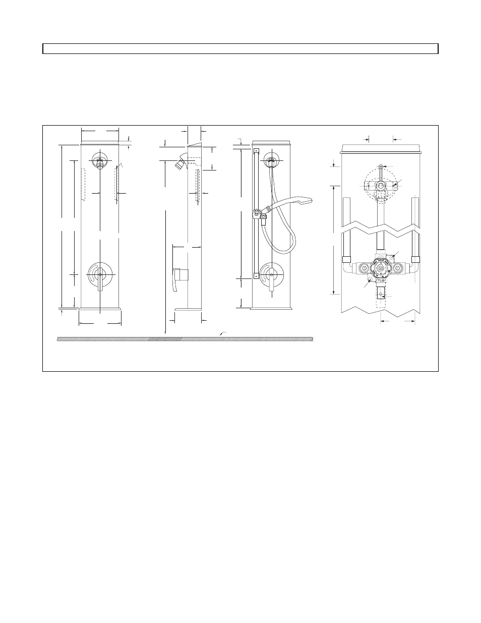
Figure 1:
Front dimensions
Hydropanel II Model 4504000
Figure 2:
Side dimensions
Hydropanel II Model 4504000
Figure 3:
Front dimensions
Hydropanel II Model 4504004.
3-5/16"
[84]
23-1/2"
[597]
A
C
D'
D'
B
END CAP
1-3/4"
[44]
2-1/4"
[57]
Figure 4.