Powers 450 Infrared ESP HydroPanel II Infrared Sensor System User Manual
Page 3
Before reconnecting shrouding with screws, turn on water
supply and activate the sensor to test the system. Water
should flow through showerhead. Deactivate sensor and
check all connections for leaks.
Use screws to attach the shrouding to the piping bracket and
to bottom mounting bracket (Figure 4, A and C).
1) When power is supplied to the ESP system, the sensor
emits a continuous field of infrared beam.
2) A bather that steps into the range of this field activates the
sensor. The sensor sends a signal through the modular
junction box to the solenoid. The solenoid opens and allows
tempered water to flow to the showerhead.
3) When the bather steps out of sensor range, a signal is sent
to the solenoid to close and consequently stop the flow of
water.
4) If the bather does not move away from the sensor, the
shower will run until the pre-set maximum run time.
After shut-off, the system is ready for reactivation.
System Maintenance
n
Routinely (twice a year) perform the following maintenance to
ensure safe continuous operation of ESP Hydropanel units.
1. Inspect electrical connections for corrosion.
2. Check for any loose connections. Tighten if necessary.
3. Check solenoid valve for proper operation. Make sure it is
free of dirt and lime build up.
4. Check that temperature of supply water is thermostatically
controlled for safe comfortable bathing.
To clean the shower area without turning off the main water
supply, either turn off the electricity to the ESP system (if pos-
sible), or simply apply a strip of dark opaque tape over the
lens. Black electrical tape will work; it absorbs and does not
reflect the infrared light. (The sensor shouldn't activate until
the tape is removed.) A mild soap may be used to clean the
lens, but avoid abrasive cleaners; they may scratch the lens.
Maintenance and Troubleshooting
n
1.
If red LED on sensor lens (Figure 7) does not light to show
that the sensor has detected a bather:
a. Check that an object was not in front of the sensor when unit
powered up. The sensor will not operate until the object is
removed and the sensor reactivated.
b. Check that transformer feed wires are securely attached to
terminals at modular junction box and at transformer.
c. Check that power is being supplied to the transformer.
Also, use a voltmeter to check that power is being supplied
through the transformer. If power goes into the transformer
but does not come out, replace the transformer.
d. If transformer functions properly and power is supplied, but
LED still does not light, replace sensor assembly.
2. If no water flows from showerhead when bather tries to
activate sensor:
a. Check that the red "sensor activation" LED lights are on.
If not, see #1.
b. Check that the supply line is open and water is being supplied.
ESP System Test
Before attaching shrouding, the
ESP system should be tested. First,
position and support the
Hydropanel shrouding within all
cable limits (on a chair, etc.). Do not
turn on power or water supply yet.
Insert the plugs from the infra-
red sensor and the solenoid into the ports on the Modular
Junction Box marked JP1 and JP2. Either plug can go into
either port on the MJB.
Supply power to the transformer, and activate the infrared
sensor by moving an object in front of it. The sensor activation
light on the front of the sensor lens (Figure 6) will turn on to
show proper sensor activation.
ESP Shower Sensitivity Adjustments
Each ESP Infrared Sensor has a potentiometer to adjust range
distance from 2" to 48". The sensor is factory set at 18"—
useful for most applications,
depending on reflectivity of
skin, room lighting, etc.
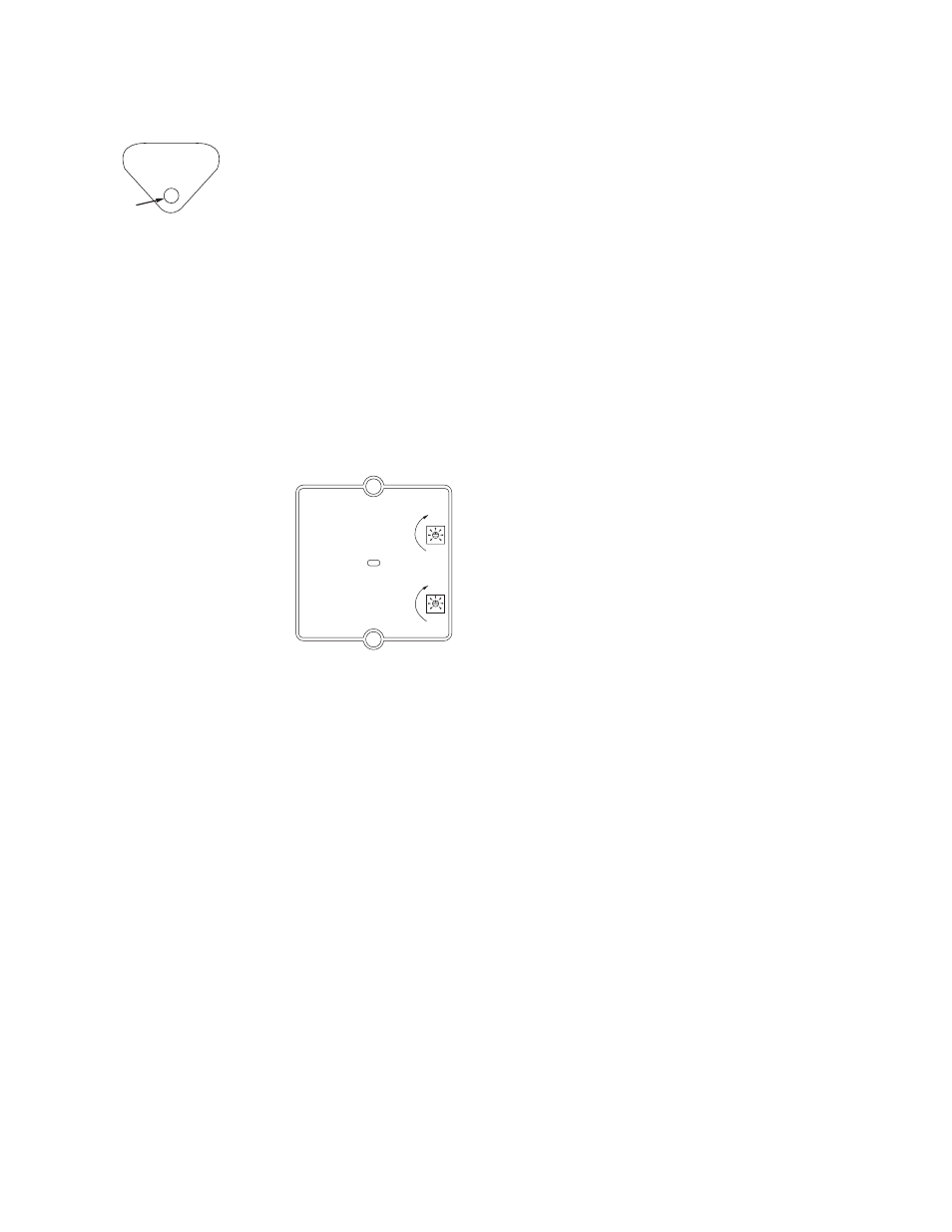
To adjust, locate the top dial
on the back of the Infrared
Sensor (Figure 7). With a small
screwdriver, rotate the dial in
small increments, clockwise
for more distance, counter-
clockwise for less. Turn dial
carefully; over-adjusting can
damage the potentiometer.
After each adjustment, test the shower.
ESP Shower Time Adjustments
Although each ESP system will shut off the shower when a
bather steps away from the sensor, it also has a potentiom-
eter to set a maximum run-time, from 0 to 14 minutes. Factory
setting is 14 minutes.
To adjust, locate the bottom dial on the back of the Infrared
Sensor (Figure 7). With a small screwdriver, rotate the dial in
small increments, clockwise for more time, counter-clockwise
for less. Turn dial carefully; over-adjusting can damage the
potentiometer. After each adjustment, test and time the
shower.
Reattach the Shrouding
The bottom bracket (Figure 4,D) will attach to the wall
19-1/4" below showerhead height (see Figure 3). Use the
bracket as a template to mark positions for two mounting
holes. Drill holes and attach the bracket.
The chrome plated end cap (Figure 4)
on top of the shrouding
has a section marked to be broken out for vertical and horizon-
tal piping clearance. To remove the marked piece, hit it sharply
with a hammer. Do not remove the entire end cap from the
shrouding.
Connect the outlet side of the solenoid to the showerhead pip-
ing by sliding the showerhead nipple (with the shrouding unit)
into the piping assembly.
IS-P-450S Page 3
Red
indicator light
Range
Distance
(In)
Run Time
(Min.)
+
–
+
–
20
40
0
14
0
9
Figure 6.
Figure 7.
Installation, Continued
n
Operation
n