Kenco Engineering SmartSonic Transmitter (Integral) User Manual
Page 2
Page 2
GENERAL DESCRIPTION
The SmartSonic Acoustic Wave Transmitter is designed for high accuracy level measurement of a variety of liquids. The
SmartSonic Integral can also be used for Open Channel Flow Measurement.
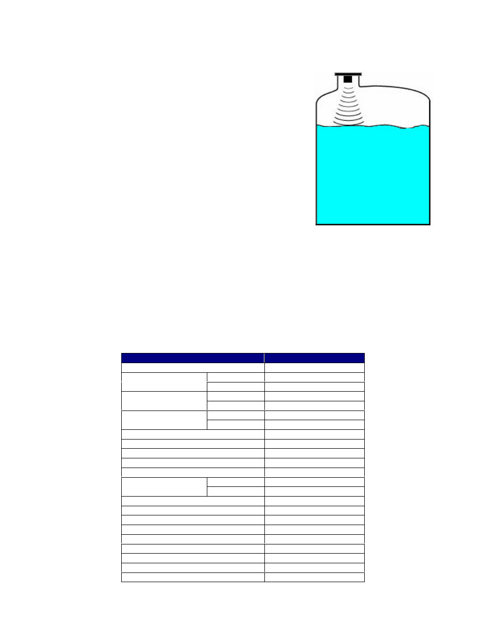
PRINCIPLE OF OPERATION
MODEL DESCRIPTION
P2W-L1-ABF-NE – Integral with 2” Polypropylene Sensor
P2W-L1-AKF-NE – Integral with 2” PVDF (Kynar) Sensor
INSTALLATION
Unpack the transmitter carefully. Inspect all units for damage. Report any damage to carrier immediately. Check the
contents against the packing slip and purchase order. Kenco’s SmartSonic Acoustic Wave Transmitters are
manufactured to the highest quality standards. These instruments use electronic components that can be damaged by
static electricity. Make sure that you are properly grounded before starting installation. Insure that all electrical
connections are properly made, and that there are no “floating” connections.
SPECIFICATIONS
Description
Specification
Power Supply
12-28 Vdc
Short Range
16 feet
Maximum Range
Long Range
49 feet
Short Range
0.8 feet
Minimum Dead Zone
Long Range
1.9 feet
Short Range
15.2 feet
Maximum Span
Long Range
47.1 feet
Frequency
25 kHz
Output Signal
4-20mA
Loop Resistance
750Ω @ 28Vdc
Diagnostic / Failure Alarm
22 mA
Wave Angle
5º @ 3db
Display
4 Character LCD
User Interface
Keypad
4 Button
Process Connection
2” NPT
Temperature Range
-40ºF to 158ºF
Pressure Range
-2 to 30psig
Accuracy
±0.25% of max. range
Resolution
0.04” (1 mm)
Enclosure Material
ABS + UV
Transducer Material
ECTFE coated aluminum
Cable Entry
½” NPT
Weight
3.1 lbs
The SmartSonic Transmitters consist of two main components:
•
The Electronics
•
The Sensor (Transducer)
The transducer contains a piezoelectric crystal that converts an
electrical signal from the electronics, into acoustic (sound) waves.
These acoustic waves are directed through the air toward the process
media surface. They are then reflected off of this surface and returned
to the transducer. The piezoelectric crystal then converts the received
waves into an electrical signal which is analyzed by the electronics.
The time difference between the transmitted wave and the received
wave is proportional to the distance from the face of the transducer to
the process media surface. This distance is used by the electronics to
calculate level or open channel flow in the units selected by the
operator.
Process
Media
Air
Acoustic
Waves