Rudder and elevator servo installation – E-flite Ultimate 20-300 10 ARF User Manual
Page 22
22
E-flite Ultimate 20-300 Assembly Manual
Rudder and Elevator Servo Installation
Required Parts
Fuselage
Servo (2)
Control horn
Silicone clevis retainer (2)
Control horn backplate
Nylon connector backplate (2)
Machine screw, 2mm x 4mm (2)
9-inch (228mm) servo extension
12-inch (305mm) servo extension
Lightweight screw lock connector (2)
Servo linkage, 4-inch (98mm) (2)
Required Tools and Adhesives
Medium CA
Thin CA
Side cutters
Hobby knife
Low-tack tape
Pin drill
Drill bit: 1/16-inch (1.5mm) Phillips screwdriver: #1
Felt-tipped pen
1. Slide the control horn into the pre-drilled holes in the
rudder. Use a felt-tipped pen to mark the area around
the base of the control horn. Remove the horn and use
a hobby knife to cut the covering away from the area
inside the outline. Use medium CA to attach the control
horn to the rudder. Install the control horn backplate on
the opposite side of the control horn to secure its position.
Remove the covering under this also.
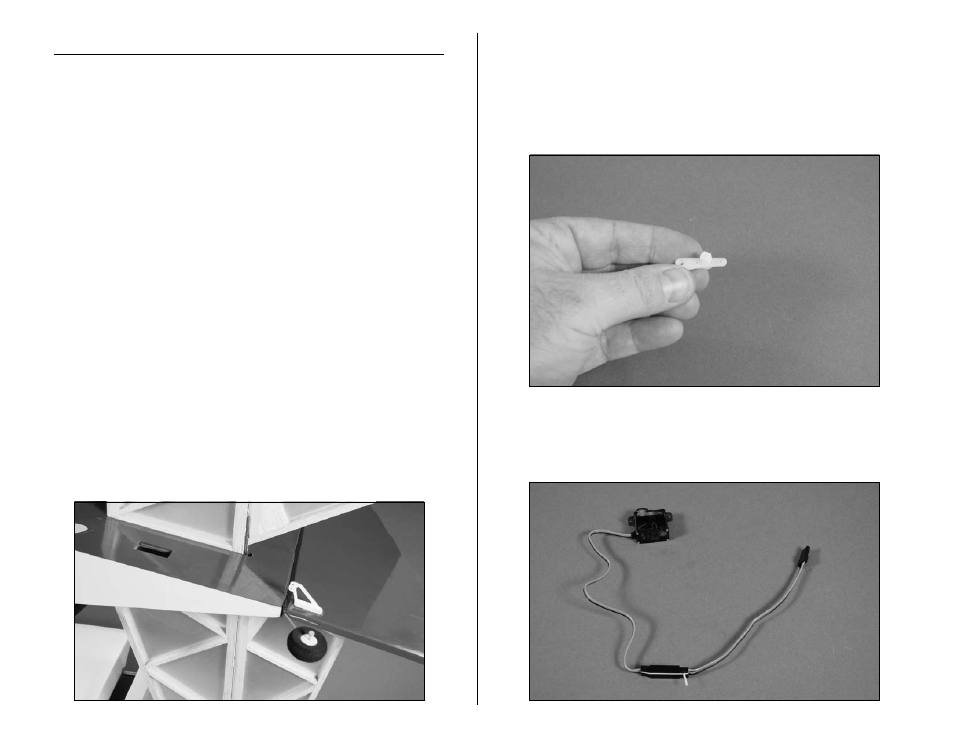
2. Prepare a long 3D servo horn by enlarging the hole
1/2-inch (13mm) from the center of the servo horn with a
pin drill and 1/16-inch (1.5mm) drill bit. After removing
the webbing from the underside of the horn, secure the
connector to the horn. Remove the excess from the horn
using side cutters.
3. Secure a 9-inch (228mm) servo extension to the
elevator servo so it will not unplug inside the fuselage.
Use a 12-inch (305mm) servo extension for the rudder.