Aileron servo installation – E-flite Ultimate 20-300 10 ARF User Manual
Page 10
10
E-flite Ultimate 20-300 Assembly Manual
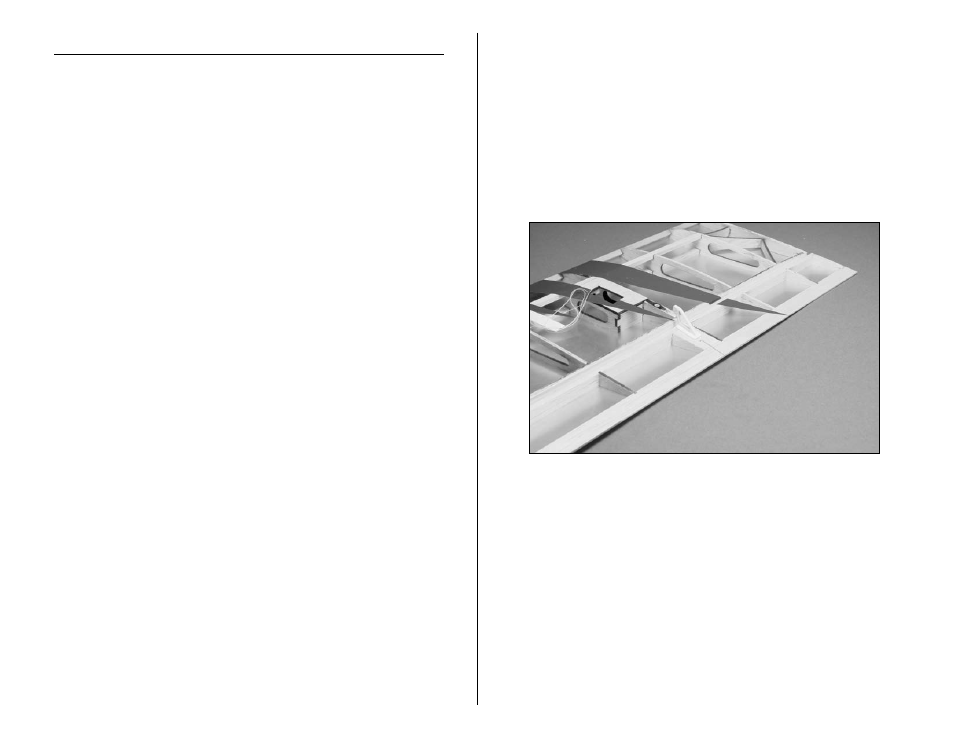
Aileron Servo Installation
Required Parts
Top wing
Bottom wing
Control horn (2)
Interconnect horn (4)
Aileron servo (2)
Silicone clevis retainer (2)
Nylon connector backplate (2) Machine screw, 2mm x 4mm (2)
6-inch (152mm) servo extension (2)
Lightweight screw lock connector (2)
Servo linkage, 2.5-inch (62mm) (2)
Required Tools and Adhesives
Medium CA
Thin CA
Side cutters
Hobby knife
Low-tack tape
Pin drill
Drill bit: 1/16-inch (1.5mm) Phillips screwdriver: #0, #1
Felt-tipped pen
1. Slide the control horn into the pre-drilled holes in
the aileron. Use a felt-tipped pen to mark the area
around the base of the control horn. Remove the
horn and use a hobby knife to cut the covering away
from the area inside the outline. Use side cutters to
trim 2-3mm off of the aft lug on the control horn.
This will eliminate the lug protruding through the
other side of the aileron. Use medium CA to glue the
control horn in the holes in the aileron. Make sure
the horn rests flush with the surface of the aileron.
Note: The aileron control horns do not require
back plates.