Stabilizer installation – E-flite Ultimate 20-300 10 ARF User Manual
Page 15
15
E-flite Ultimate 20-300 Assembly Manual
Note: The servo horn should be installed parallel to the
hinge line to produce the correct linkage geometry.
Important: The suggested digital servos will require
programming before setting the control throws. This will
be covered in the manual before the throws are set.
18. Use a 2mm x 4mm machine screw and #1 Phillips
screwdriver to secure the linkage to the connector.
Hint: The aileron should be centered and the servo
horn aligned with the aileron hinge line before
tightening the screw.
19. Repeat Steps 10 through 18 for the remaining
servo linkage.
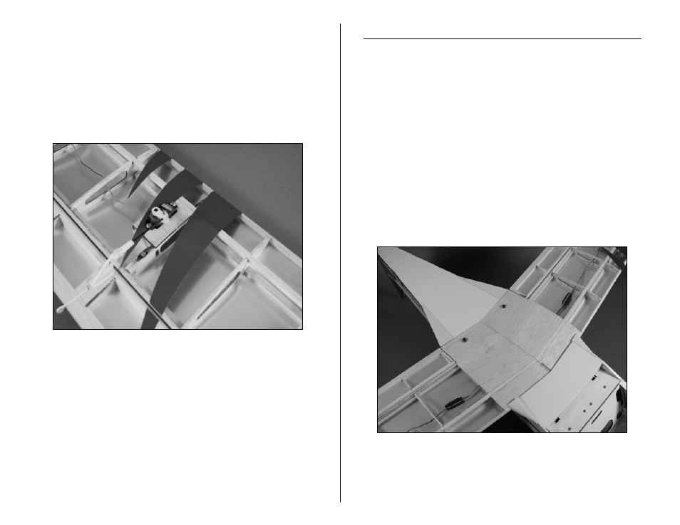
Stabilizer Installation
Required Parts
Bottom wing
Fuselage
#4 washer, silver (2)
Stabilizer
Socket head screw, 4-40 x 1-inch (2)
Elevator joiner wire
Required Tools and Adhesives
Ball driver: 3/32-inch
Felt-tipped pen
Hobby knife
Thin CA
Sandpaper
1. Attach the bottom wing to the fuselage using a two
4-40 x 1-inch socket head screws and two #4 washers.
Use the larger silver washers when attaching the bottom
wing. Use a 3/32-inch ball briver to tighten the socket
head screws.