Aileron servo installation – E-flite Extra 300 32e ARF User Manual
Page 6
6
E-flite Extra 300 32e ARF Assembly Manual
Aileron Servo Installation
Required Parts
Nylon clevis (2)
Clevis retainer (2)
Assembled wing panel (right and left)
Control horn screw with hardware (2)
Servo extension, 6-inch (152mm) (2)
Aileron linkage wire, 2
1
/
2
-inch (64mm) (2)
Radio system
Servo with accessories (2)
Heavy-duty servo horn (2)
Nylon control horn (2)
Required Tools and Adhesives
Pliers
Phillips screwdriver: #1, #2
String
Pencil
Thin CA
Threadlock
Pin vise
String
Drill bit: 1/16-inch (1.5mm), 5/64-inch (2mm)
1. Remove the tapered nut and one countersink
from the control horn screw. Slide the screw and
remaining countersink into the hole in the aileron.
The screw must exit to the bottom of the wing.
Always use threadlock on metal-to-metal fasteners
to prevent them from vibrating loose.
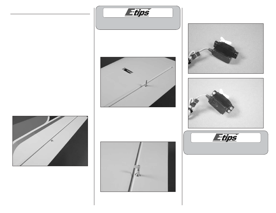
2. Slide the countersink back onto the control
horn screw. The tapered nut is then threaded on
the screw to secure its position on the aileron.
Use a #2 Phillips screwdriver and pliers to
tighten the hardware.
3. Thread the nylon control horn on the control
horn screw. The top of the control horn must be
flush with the top of the screw when installed. It
may be necessary to use a #2 Phillips screwdriver
to keep the control horn screw from rotating when
installing the control horn.
4. Prepare the servo by installing the grommets
and brass eyelets as described in the instructions
with the servo or your radio system.
Prepare the elevator and rudder
servos at this time as well.