Elevator installation – E-flite Extra 300 32e ARF User Manual
Page 18
18
E-flite Extra 300 32e ARF Assembly Manual
Elevator Installation
Required Parts
Fuselage assembly Control horn assembly
Nylon control horn Elevator joiner wire
CA hinge (6)
Clevis
Clevis retainer
Elevator (left and right)
Pushrod wire, 3
1
/
2
-inch (90mm)
Plastic packaging from model
Required Tools and Adhesives
Scissors
Medium grit sandpaper
Low-tack tape
Thin CA
30-minute epoxy
Toothpick
T-pins
Hobby knife with #11 blade
Pin vise
Drill bit: 1/16-inch (1.5mm)
Threadlock
Phillips screwdriver: #2
Pliers
Mixing cups
Paper towels
Rubbing alcohol
Mixing sticks
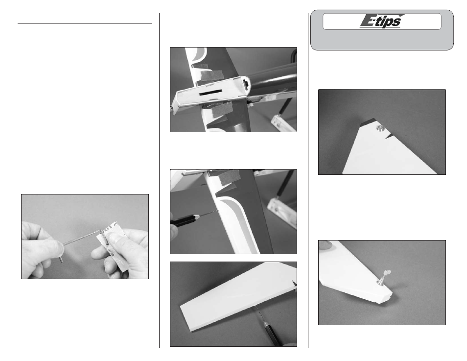
1. Use medium grit sandpaper to lightly sand the
ends of the elevator joiner wire. This will provide a
surface for the epoxy to adhere to.
2. Cut two strips of the clear plastic film the model
was packaged in using scissors. Use low-tack tape
to tape the plastic to the elevators so the joiner wire
isn’t accidentally glued to the stabilizers.
3. Use a pin vise with a 1/16-inch (1.5mm) drill
bit to drill a hole in the center of each of the hinge
slots in both the elevators and stabilizers.
Always use threadlock on metal-to-metal fasteners
to prevent them from vibrating loose.
4. Remove the tapered nut and one countersink
from the control horn screw. Slide the screw and
remaining countersink into the hole in the elevator.
The screw must exit to the bottom of the elevator.
5. Slide the countersink back onto the control horn
screw. The tapered nut is then threaded on the
screw to secure its position on the elevator. Use
a #2 Phillips screwdriver and pliers to tighten the
hardware. Thread the nylon control horn onto the
control horn screw so it is flush with the end of the
screw as shown.