Landing gear and wheel installation – E-flite Extra 300 32e ARF User Manual
Page 12
12
E-flite Extra 300 32e ARF Assembly Manual
Landing Gear and Wheel Installation
Required Parts
Fuselage assembly Axle with hardware (2)
#4 washer (5)
Aluminum landing gear
Main wheel (2)
Wheel pant (left and right)
4-40 x 1-inch socket head screw (3)
4-40 x 3/8-inch socket head screw (2)
Required Tools and Adhesives
Hex wrench or ball driver: 1.5mm, 3/32-inch
Threadlock
Nut driver: 7mm
Flat file
Pliers or adjustable wrench
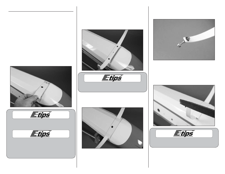
1. Remove the landing gear fairing from the
fuselage and set it aside.
Always use threadlock on metal-to-metal fasteners
to prevent them from vibrating loose.
The landing gear can only be installed in one
direction. If the holes in the landing gear don’t
align with the blind nuts in the fuselage, rotate
the gear front-to-back so the holes are aligned
with the blind nuts installed in the fuselage.
2. Attach the landing gear using two (2) 4-40 x
1-inch socket head screws and two (2) #4 washers.
Use a 3/32-inch hex wrench or ball driver to
tighten the screws. Only install the outer screws
as shown in the photo. The center hole is for the
attachment of the landing gear fairing.
Always use threadlock on metal-to-metal fasteners
to prevent them from vibrating loose.
3. Use a 4-40 x 1-inch socket head screw and
#4 washer to attach the landing gear fairing to
the fuselage.
4. Attach the axle to the landing gear. Use a 7mm
nut driver to tighten the locknut while holding the
axle with an adjustable wrench or pliers.
5. Use a 1.5mm hex wrench to loosen the setscrew
in the wheel collar to remove the collar. Use a file
to make a flat area for the first 1/4-inch (6mm) on
the bottom of the axle. This will provide an area to
tighten the setscrew, making it more secure.
Always use threadlock on metal-to-metal fasteners
to prevent them from vibrating loose.