Configuration settings (continued), Step 6cs – Watts W100T Twin Alternating Series User Manual
Page 11
W100T Twin Alternating Series Softeners
11
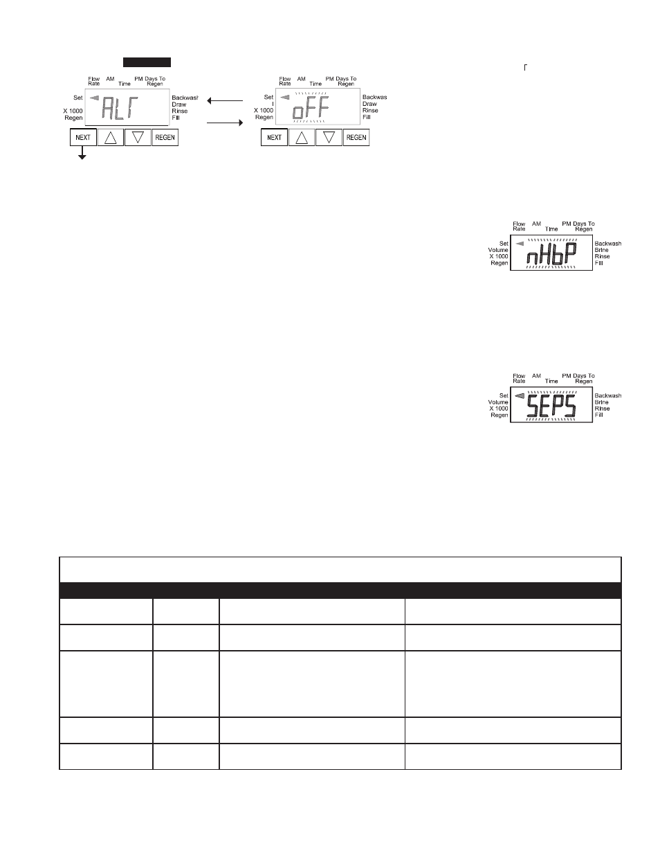
Step 6CS
This display will not appear if 1.0 was selected in Step
2CS. Allows selection of one of the following using
▲or ▼
:
• the Control Valve to have no hard water bypass;
• the Control Valve to act as an alternator; or
• the Control Valve to have a separate source during
the regeneration cycle.
Select OFF when none of these features are used.
Only use No Hard Water Bypass Valves or Motorized Alternating Valves (MAV) with these selections. No Hard Water Bypass Valves (1” or 1.25”
V3070FF or V3070FM) are not designed to be used with the alternator or separate source functions. The V3063 and V3063BSPT motorized
alternating valves are not designed to be used as a no hard water bypass or separate source inlet if the pressure differential is more than 60 psi.
Prior to starting the programming steps, connect the interconnect cable to each control valve board’s three pin connector labeled
“INTERCONNECT”. Also connect the meter cord to either control valve to the three pin connector labeled “METER”.
Valve Programming Steps
Configuration
Settings
Step 4CS
Select Volume
Set Volume
Configuration
Settings
Step 5CS
Set regeneration time option to “On O”.
Set regeneration time option to “On O”.
Configuration
Settings
Step 6CS
Set to ALTA
Connect ALTA valve to the MAV’s A port and
connect the MAV’s two pin wire connector
to the two pin connector labeled “DRIVE” on
the ALTA valve
Set to ALTb
Connect ALTb valve to the MAV’s B port. No
connections between the ALTB valve and the MAV
are made.
Installer Display
Setting
Step 2I
Enter the Volumetric Capacity for the System
Enter the Volumetric Capacity for the System (the
same as Valve A)
Installer Display
Setting
Step 3I
Set Day Over ride to “oFF”
Set Day Over ride to “oFF”
Step 6CS
Step 1CS
Step 2CS
Step 3CS
Step 4CS
Step 5CS
EXIT TO
DISPLAY
SCREENS
Step 1CS
Step 2CS
Step 3CS
Step 4CS
Step 5CS
EXIT TO
DISPLAY
SCREENS
Volume
Volume
C. Selecting the Control Valve to act as an alternator:
519.0 and higher = Use 3-wire Interconnect Cables for all communication between units.
518.3 and lower = Use 2-wire Interconnect Cables for twin alternators with independent flow meters.
A. Configuring the Control Valve for No Hard Water Bypass Operation:
Select nHbP for control operation. For no hard water bypass operation the three wire connector is not
used.
Selection requires that a connection to MAV or a No Hard Water Bypass Valve is made to the two pin
connector labeled ALTERNATOR DRIVE located on the printed circuit board. If using a MAV, the A port
of the MAV must be plugged and the valve outlet connected to the B port. When set to nHbP the MAV
will be driven closed before the first regeneration cycle that is not FILL or SOFTENING or FILTERING,
and be driven open after the last regeneration cycle that is not FILL.
NOTE: If the control valve enters into an error state during regeneration mode, the no hard
water bypass valve will remain in its current state until the error is corrected and
reset.
B. Configuring the Control Valve for Separate Source Operation:
Select SEPS for control operation. For separate source operation the three wire connector is not used.
Selection requires that a connection to a Motorized Alternator Valve (MAV) is made to the two pin
connector labeled ALTERNATOR DRIVE located on the printed circuit board. The C port of the MAV
must be connected to the valve inlet and the A port connected to the separate source used during
regeneration. The B port must be connected to the feed water supply.
When set to SEPS the MAV will be driven closed before the first regeneration cycle, and be driven open
after the last regeneration cycle.
NOTE: If the control valve enters into an error state during regeneration mode, the MAV will
remain in its current state until the error is corrected and reset.
NOTE: If the control valve is in an error state during regeneration mode the MAV will close the B port and keep open the A port
until the error is corrected and reset.
Configuration Settings (continued)