Duo-touch, Models at-..m-2a two-hand control modules, Theory of operation – Banner DUO-TOUCH Two-Hand Control Modules User Manual
Page 4: Mechanical installation
DUO-TOUCH
®
– Models AT-..M-2A Two-Hand Control Modules
4
P/N 47550 rev. E
Banner Engineering Corp.
•
Minneapolis, MN U.S.A.
www.bannerengineering.com • Tel: 763.544.3164
Theory of Operation
The input circuit of the DUO-TOUCH Safety Module requires simultaneous actuation
(within 0.5 seconds of each other) of both two-hand control actuators to generate an
output signal.
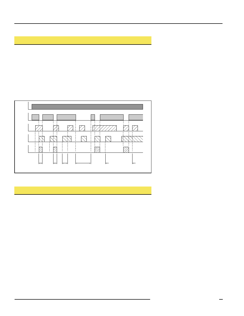
The timing diagram in Figure 2 illustrates that an output signal from the DUO-TOUCH
Safety Module occurs only if switches #1 and #2 (SW1 and SW2) are actuated within
0.3 seconds of each other (300 ms typical, not more than 500 ms under single-fault
conditions). The output signal drops within 25 milliseconds following the release of
either switch. The device output does not reenergize until both hand controls are dis-
engaged, and then simultaneously re-actuated. This logic reduces the possibility of
defeating the two-hand control system by tying down one or both actuators.
Mechanical Installation
The DUO-TOUCH Safety Module must be installed inside a NEMA 3 (IEC IP54) rated, or
better, enclosure. It is not designed for exposed wiring. Safety Module dimensions are
shown in Figure 6. The device mounts directly onto standard 35 mm DIN rail.
Heat Dissipation Considerations
For reliable operation, the user must ensure that the operating specifications are not
exceeded. The enclosure must provide adequate heat dissipation, so that the air closely
surrounding the Module does not exceed the maximum operating temperature stated in
the Specifications (page 11). Methods to reduce heat build-up include venting, forced
airflow (e.g., exhaust fans), adequate enclosure exterior surface area, and spacing
between modules and other sources of heat.
Power
< 300 ms
(Typ.)
< 300 ms
> 300 ms
Feedback Open
(Red LED ON)
SW1 tied down
SW2 tied down
Feedback
Loop*
SW1
SW2
Output
Figure 2. DUO-TOUCH Safety Module AT-..M-2A timing diagram