Repairs, Specifications – Banner DUO-TOUCH SG Two-Hand Control Safety Modules User Manual
Page 11
the ability to solve problems relating to the installation, maintenance and use of the Safety System). Keep a copy of the test
results on or near the machine.
WARNING: EDM Monitoring
If the System is configured for “No Monitoring,” it is the user’s responsibility to ensure that this
does not create a hazardous situation.
1. Perform the daily checkout procedure.
2. Perform the initial checkout procedure.
3. Calculate the separation distance, and verify that the actuating devices are far enough away from the nearest hazard point. Relo-
cate the actuating devices, if necessary.
4. Verify that the actuating devices are positioned to require the use of both hands for operation, and are protected from false or
inadvertent operation.
5. Inspect the machine controls and the connections to the Safety Module to ensure that wiring is correct and that no modifications
have been made which could adversely affect the System.
Repairs
NOTE: Do not attempt any repairs to the Safety Module. It contains no field-replaceable components. Return it to the factory for warranty
repair or replacement.
CAUTION: Abuse of Module After Failure
If an internal fault has occurred and the Module will not reset, do not tap, strike, or otherwise attempt to
correct the fault by a physical impact to the housing. An internal relay may have failed in such a man-
ner that its replacement is required.
If the Module is not immediately replaced or repaired, multiple simultaneous failures may accumu-
late such that the safety function can not be guaranteed.
If it becomes necessary to return a Safety Module to the factory:
1. Contact Banner Factory Application Engineering at the address or at the
numbers listed in this document. They will attempt to troubleshoot the sys-
tem from your description of the problem. If they conclude that a compo-
nent is defective, they will issue an RMA (Return Merchandise Authoriza-
tion) number for your paperwork, and give you the proper shipping ad-
dress.
2. Pack the component carefully. Damage which occurs in return shipping is
not covered by warranty.
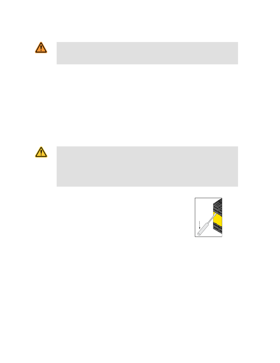
Figure 7. To remove a terminal block, insert a
small screwdriver into the slot as shown; pry to
loosen
Specifications
Supply
24V dc ±15% @ 150 mA (use a SELV-rated supply according to EN IEC 60950, NEC Class 2)
24V ac ±15% @ 150 mA, 50-60 Hz +/- 5% (use an NEC Class 2-rated transformer)
To comply with UL and CSA standards, the installation’s isolated secondary power supply circuit must incorporate a method
to limit the overvoltage to 0.8 kV.
Supply Protection Circuitry
Protected against transient voltages and reverse polarity
Overvoltage Category
Output relay contact voltage of 1V to 150V ac/dc: Category III
Output relay contact voltage of 151V to 250V ac/dc: Category II (Category III, if appropriate overvoltage reduction is
provided, as described in this document.)
AT-FM-10K Two-Hand Control Module
P/N 64137 Rev. G
www.bannerengineering.com - tel: 763-544-3164
11