Connecting the dialysis cell – Metrohm 838 Advanced Sample Processor Installation Instructions User Manual
Page 35
3.3 Fitting the accessories
838 Advanced Sample Processor, Installation
29
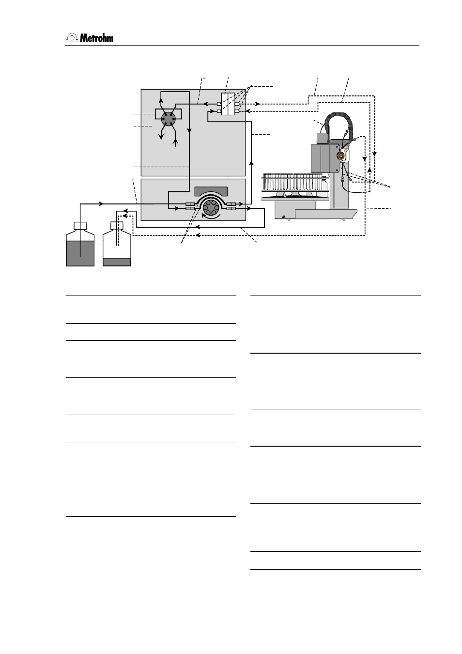
3.3.12 Connecting the dialysis cell
833 Pump Unit
820
A
Metrohm
838
Figure 24 Capillary connections for dialysis
68 PTFE capillary (6.1803.040, 1 m)
supply of the sample/acceptor solution
37 Dialysis cell (6.2729.100)
61 Pump tubing (6.1826.030)
with orange-yellow stoppers for deliv-
ery of the acceptor solution
69 Pump tubing (6.1826.040)
with black-black stoppers for delivery
of the sample
70 PEEK sample loop (6.1825.210,
20 μl)
71 Injection valve A
72 PTFE capillary (6.1803.040, 1 m)
peristaltic pump connection (838 Ad-
vanced Sample Processor channel 1
for supply of fresh sample) –dialysis cell
inlet (sample end)
73 PTFE capillary (6.1803.040, 1 m)
Dialysis cell outlet (sample end) – peri-
staltic pump connection (838 Ad-
vanced Sample Processor channel 2
for disposal of the dialysed sample so-
lution)
74 PTFE capillary (6.1803.040, 1 m)
Peristaltic pump (838 Advanced Sam-
ple Processor channel 2 for disposal
of the dialysed sample solution) – waste
container connection
75 PTFE capillary (6.1803.040, 1 m)
Peristaltic pump (833 Pump Unit
channel 1 for supply of fresh acceptor
solution) – dialysis cell inlet (acceptor
end) connection
76 PEEK capillary (6.1831.050, 40 cm)
Outlet dialysis cell (acceptor end) –
connection 1 valve A connection
77 PEEK capillary (6.1831.060, 1 m)
Connection 2 valve A – peristaltic pump
(833 Pump Unit channel 2 for dis-
posal of the acceptor solution) connec-
tion
78 PTFE capillary (6.1803.040, 1 m)
peristaltic pump (833 Pump Unit chan-
nel 2 for disposal of the acceptor solu-
tion) – waste container
64 PVDF pressure screw (6.2744.000)
Column
Eluent
Acceptor Waste
71
70
76
64
37
77
68
61
75
73
72
74
78
69
68