Mirror harness connector pinouts, Route & secure chassis harness, Pin mirror connector – Brandmotion 9002-1010 User Manual
Page 7: Pin mirror harness connector
!
"#$%&''&%"(#!"#$%)*+%"(#$!
1010 Instructions 9-30-14.doc
7 of 8
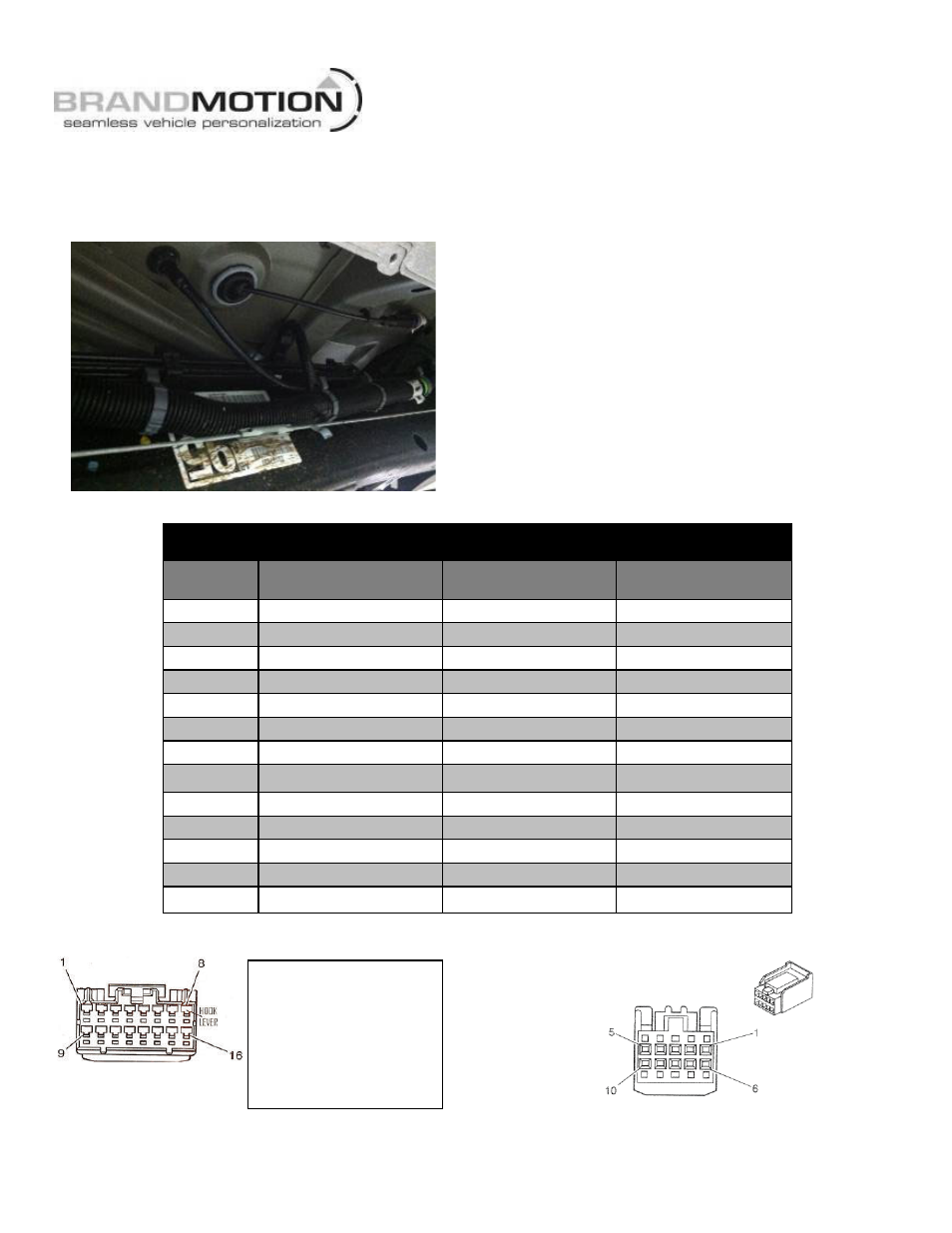
Route & Secure Chassis Harness
48. Route supplied Chassis Harness along existing
chassis harness toward rear of vehicle, staying clear
of body mounts. (Figure 28)
Figure 28
49. Connect supplied Chassis Harness to Tailgate Handle
Camera harness.
50. Secure supplied Chassis Harness along the existing
Chassis Harness using Wire Ties every 200mm
(approximately 8”). Note: Depending on vehicle
wheelbase there may be excess length in the
Chassis Harness. Loop, and secure with Wire Ties,
any excess harness length along the Body Frame
away from Mechanical areas.
51. Reconnect negative battery terminal. Tighten
negative cable nut to 5 N
!m (44 lb in).
52. Test system functionality: start vehicle, apply brake,
and shift into Reverse. The camera image should
appear in the Mirror display.
53. Re-install all previously removed trim.
Mirror Harness Connector Pinouts
WIRE
COLOR
FUNCTION
16-PIN
CONNECTOR PIN #
10-PIN
CONNECTOR PIN #
N/A
N/A
1 - 4
–
Gray
Auto Dimming (+)
5
9
White
Video (+)
6
–
Brown
Video (–)
7
–
Black
Ground
8
5
Dark Green
Reverse Signal 12V+
9
1
N/A
N/A
10
10
Purple
OnStar Keypad Output
11
3
Dark Blue
OnStar Keypad Power
12
4
Pink
Ignition Controlled 12V+
13
2 (Red & Pink)
Yellow
OnStar LED Green Signal
14
6
Orange
OnStar LED Red Signal
15
7
Red
Auto Dimming (–)
16
8
16-pin Mirror Connector
10-pin Mirror Harness Connector
\
Note: 16-pin cavities
are numbered on
the back side of the
mirror connector.
Additionally,
Brandmotion
identifies Cavity 1
with a white mark.