Installation instructions – Brandmotion 9002-1010 User Manual
Page 6
INSTALLATION INSTRUCTIONS
1010 Instructions 9-30-14.doc
6 of 8
NOTE: Only Use Steps 41 - 47 if power is not
provided from Factory 10 Pin mirror
connector!
Wire Supplied Mirror Harness
41. Use a T15 Torx bit to remove the (2) bolts securing
the driver side knee bolster.
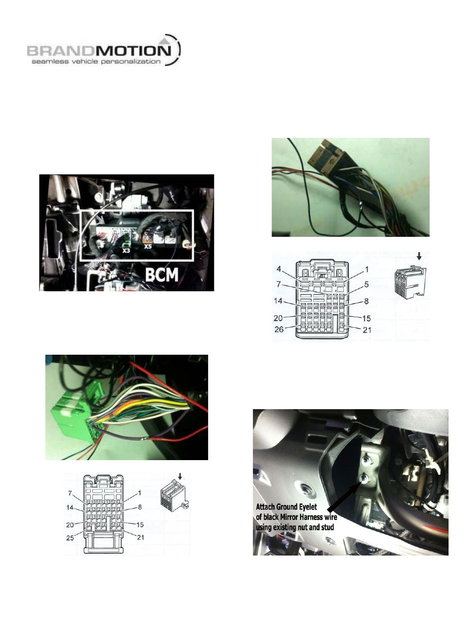
42. Locate the Body Control Module (BCM) below the
dash just to the left of the steering wheel. Note: the
BCM connectors face toward the firewall. (Figure 24)
Figure 24
43. Remove green BCM X3 Connector from the BCM.
(Figure 11). Splice Red Ignition wire of the Mirror
Harness to the Violet/Black wire in Pin 6 of the
connector (Recommended: Solder and cover with
Heat Shrink Tubing. (Figure 25)
Figure 25
Green BCM Connector X3 Pinout
44. Reinsert green BCM X1 connector in the BCM.
45. Remove the brown BCM X5 Connector from the
BCM. (Figure 11) Splice Green Reverse wire of the
Mirror Harness to the Dark Blue/Brown wire in Pin
26 of the connector (Recommended: Solder and
cover with Heat Shrink Tubing. (Figure 26)
Figure 26
Brown BCM Connector X5 Pinout
46. Reinsert brown BCM X5 connector in the BCM.
47. Attach Ground Eyelet of the black Ground wire on
the supplied Mirror Harness to chassis ground using
the stud located behind the knee bolster indicated in
Figure 27.
Figure 27