Connection description – Bird Technologies SA-1700-P User Manual
Page 17
Introduction
7
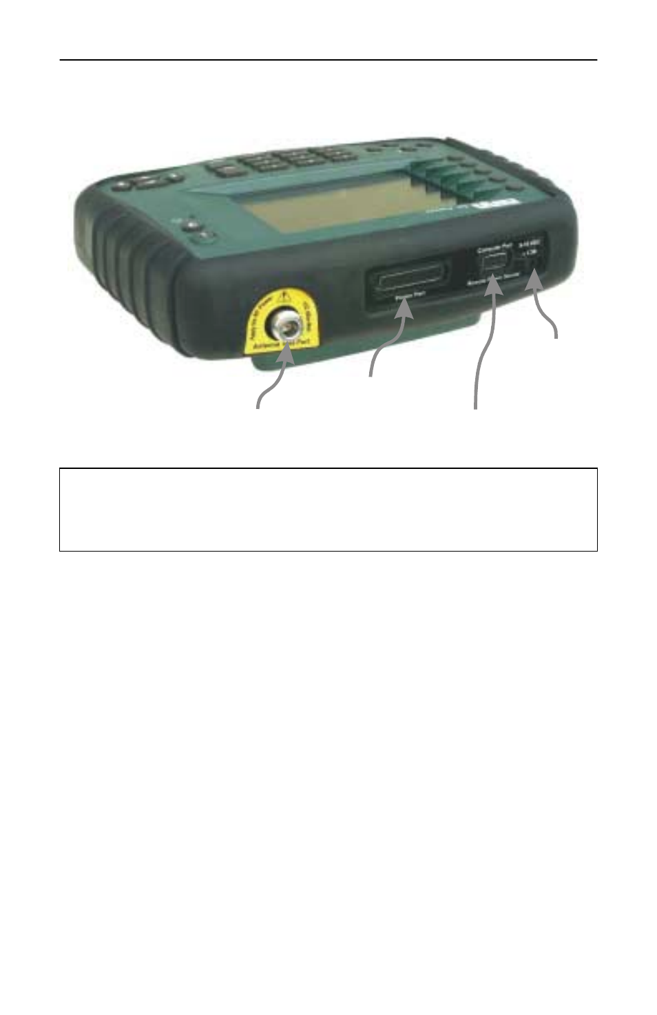
Connection Description
Antenna
Test Port
Parallel
Printer Port
Computer Port
Remote Power Sensor
DC Input
CAUTION
+22 dBm max. input
Do not apply RF power to Antenna Test Port. Exceeding the maxi-
mum input will damage the Site Analyzer.
Antenna Test Port
Standard N-type female connector. Use a
phase-stable armored cable to connect
the Site Analyzer to the antenna.
Optional Test Port Extension Cables and
adapters are listed in the Accessory
Guide Brochure.
Parallel Printer Port
25-pin (DB25) parallel connector.
Connect the Site Analyzer to a HP-type
inkjet printer. The cable is not included.
Computer/Power Sensor Port
9-pin RS-232 (DB9) serial connector.
9600 baud, 8 data bits, 1 stop bit, no
parity, and no handshake. Connect the
Site Analyzer to a PC serial port or to
Bird power sensors.
DC Input
Input for external power supplies. Plug
either the ac power supply or the
cigarette lighter adapter into the dc
input. The external supplies operate the
unit and charge the internal battery.