Five terminal interlock without power relay, Two terminal interlock, Figure 8 interlock two terminal – Bird Technologies DA40 UHF Series-Manual User Manual
Page 26: Ac power hookup
Bird Technologies
12
Five Terminal Interlock without Power Relay
This interlock has five terminals on the load’s interlock connection,
see Figure 7. T-1 and T-2 are the terminals for a thermal overload
switch which trips if the load’s operating temperature is exceeded. The
switch is normally closed, SPST with a rating of 10 A @ 120 VAC and 5
A @ 250 VAC. Terminals SL, P-1, and P-2 are not used.
Note:
Line power interlock terminals will not function
without the line power relay installed. See "Five Terminal
Interlock with Power Relay" on page 10 for relay instructions.
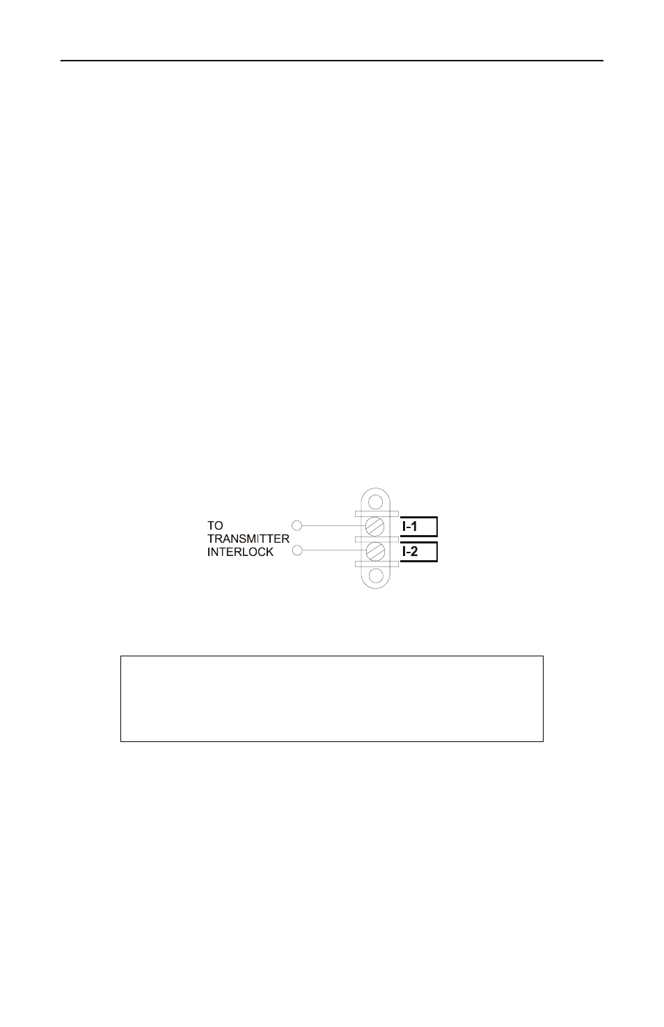
Two Terminal Interlock
This interlock has two terminals on the load’s interlock connection,
see Figure . I-1 and I-2 are the terminals for a thermal overload switch
which trips if the load’s operating temperature is exceeded. The switch
is normally closed, SPST with a rating of 10 A @ 120 VAC and 5 A @
250 VAC.
Figure 8 Interlock Two Terminal
AC Power Hookup
The AC power supply required for this unit is 115/230 V @ 50/60 Hz, 1Φ
depending on the model number. See "AC Power Required" on page 28
for current requirements. AC power is supplied through a 3-wire power
cable or by hard wiring the unit with standard 1/2 inch conduit.
AC Power Wire Size Requirements
For DA5 through DA25 and 230 VAC DA40 loads use 18 GA. Copper
stranded insulated wire rated for 1000 VAC and 80°C. For the
115VAC DA40 loads use 14 GA. Copper stranded insulated wire rated
for 1000 VAC and 80°C.
CAUTION
Check the local electrical code for proper AC hookup
prior to operation of the unit. Make sure the neutral
or return hookup is only used for that purpose.