Interlock connection, Figure 5 setup for single external interlock, Five terminal interlock with power relay – Bird Technologies DA40 UHF Series-Manual User Manual
Page 24
Bird Technologies
10
Interlock Connection
Units are equipped with one of three interlock systems. Refer to the
instructions on the following pages appropriate for individual inter-
locks. When connecting terminals to an external interlock, refer to the
transmitter instructions.
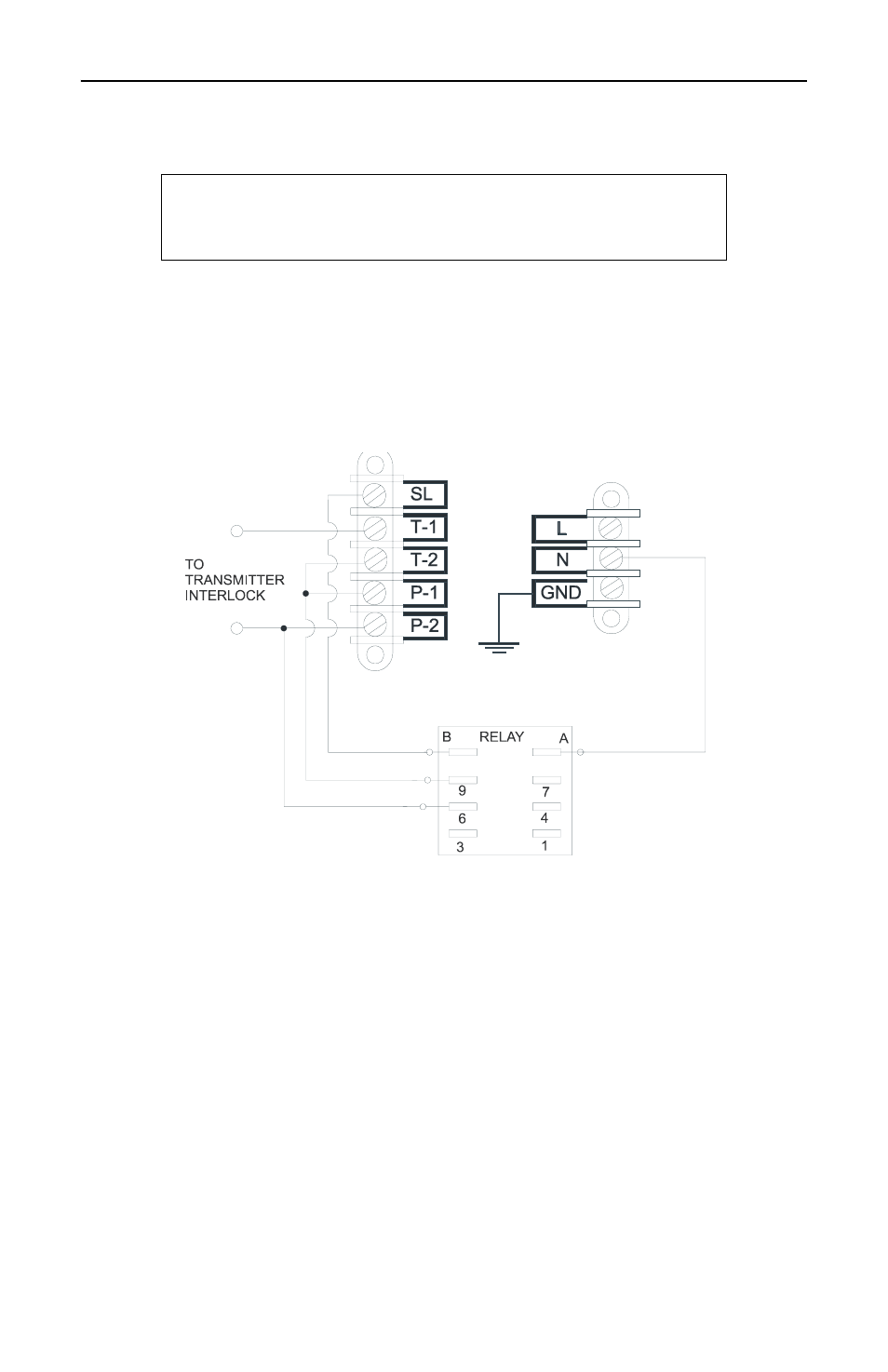
Figure 5 Setup for Single External Interlock
Five Terminal Interlock with Power Relay
This interlock has five terminals on the load’s interlock connection as
well as an external relay. T-1 and T-2 are the terminals for a thermal
overload switch which trips if the load’s operating temperature is
exceeded. P-1 and P-2 are the terminals for a line power switch which
trips if line power fails. Both switches are normally closed, SPST with
a rating of 10 A @ 120 VAC and 5 A @ 250 VAC.
Note:
Line power interlock terminals will not function without
the line power relay installed.
CAUTION
Connect interlock before RF operation.