Figure 3 duct mounting location, Access panel, Figure 4 power entry box – Bird Technologies DA40 UHF Series-Manual User Manual
Page 23
Installation
9
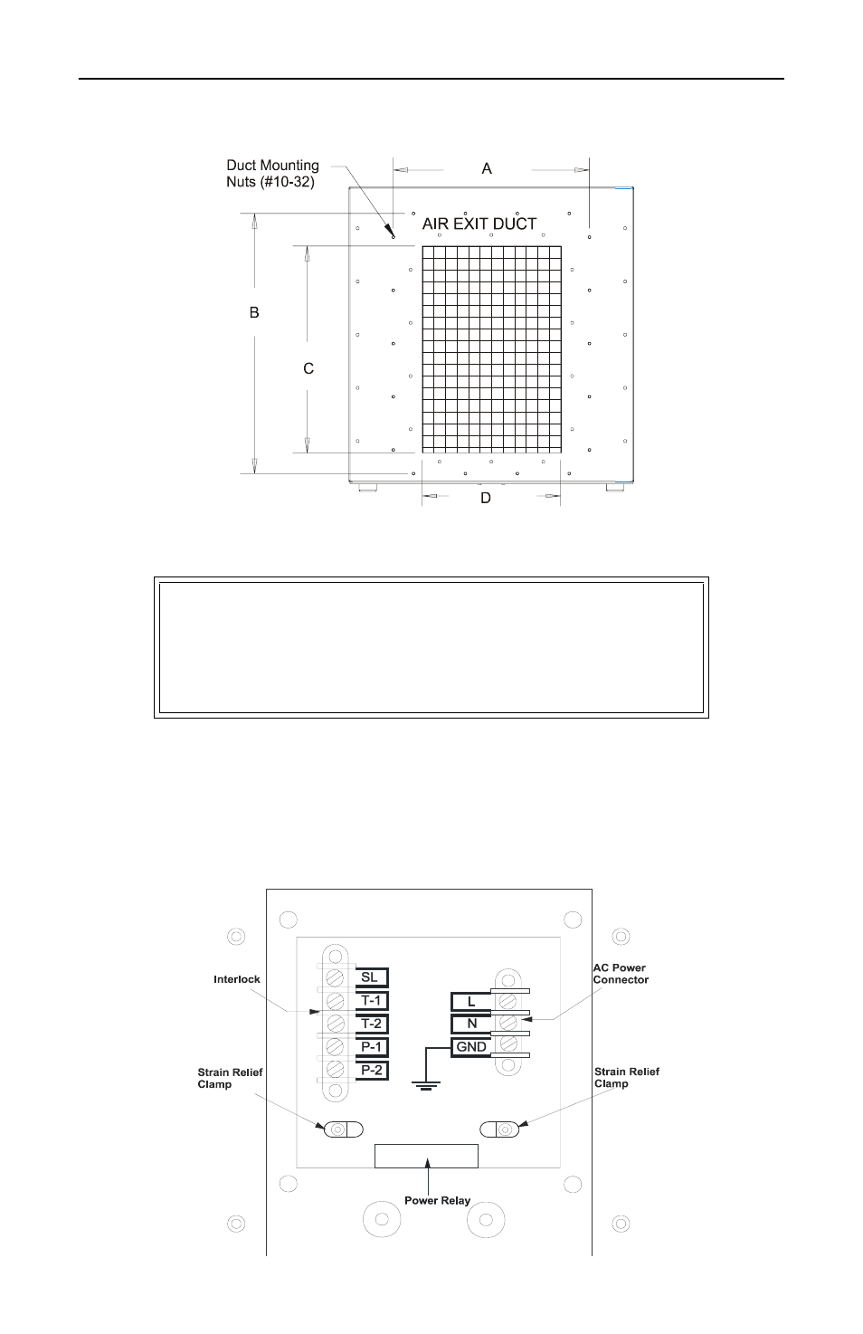
Figure 3 Duct Mounting Location
Access Panel
Remove the access panel on the front of the load to connect interlocks,
attach AC power cables, or hard-wire the unit to AC power. For the loca-
tion of the access panel see the outline drawing (Figure 1). See Figure 4
for the contents of the power entry box behind the access panel.
Figure 4 Power Entry Box
WARNING
Turn off AC power and RF power before removing or
replacing the access panel; the potential for
electrical shock exists.
This manual is related to the following products: