Bird Technologies DA40 UHF Series-Manual User Manual
Page 25
Installation
11
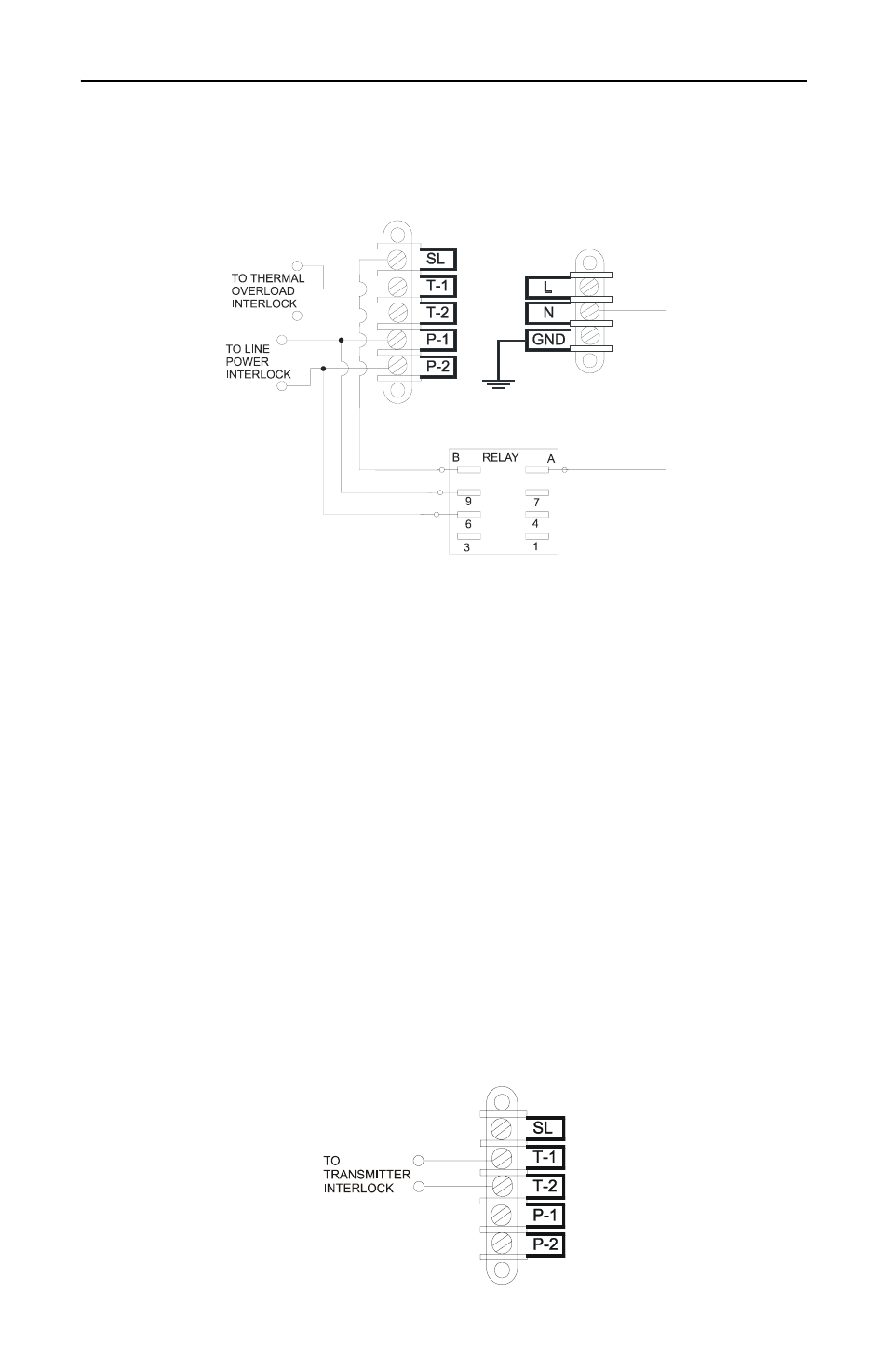
To connect both interlocks to a single interlock circuit, wire the
interlock as follows (see Figure 6):
Figure 6 Setup for Separate Thermal and Line Power Interlocks
1. Connect terminals T-2 and P-1.
Note:
T-2 and P-1 are connected when shipped from the
factory.
2. Connect terminal SL to relay pin B. Connect relay pin A to the AC
power NUT terminal.
3. Connect terminal P-1 to relay pin 9. Connect terminal P-2 to relay pin 6.
4. Connect terminals T-1 and P-2 to the transmitter interlock circuit.
For separate thermal and line power interlocks, set the inter-
lock as follows (see Figure 7):
1. Remove the connector between T-2 and P-1.
2. Connect terminals T-1 and T-2 to the thermal overload circuit on
the transmitter.
3. Connect terminal SL to relay pin B. Connect relay pin A to the AC
power NUT terminal.
4. Connect terminal P-1 to relay pin 9. Connect terminal P-2 to relay pin 6.
5. Connect terminals P-1 and P-2 the line power interlock circuit on
the transmitter.
Figure 7 Five Terminal Interlock without Power Relay