Setting the frequency span, Setting the distance and units – Bird Technologies SK-4000-TC-Manual User Manual
Page 31
19
Setting the Frequency Span
T
1
F
--------
N
1
–
F
max
F
min
–
-------------------------------
=
=
Note:
N = Test points
F
min
= Start frequency
F
max
= End frequency
The fuzzy distance be recalculated as the max distance for DTF test.
DTF
max
C V
p
T
2
----------------------------
C V
p
N
1
–
2
F
max
F
min
–
-------------------------------------------
=
=
Note:
C = Speed of light
Vp = Start frequency
Example - For a cable with a dielectric constant of 1, the velocity
percentage is 100% and 201 data points are chosen, then the Site-
Hawk Analyzer should be set to a frequency span of 0.1 MHz
(85MHz to 85.1MHz). The maximum distance of fault will be
299,792.458 meters.
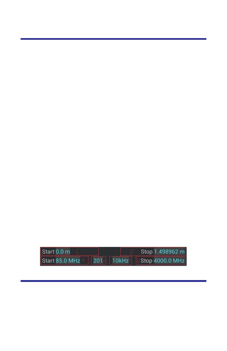
1.
Determine the frequency span.
2.
Choose how many data points are to be measured.
3.
Choose a velocity propagation percentage that is closest to the cable .
4.
Press the 3-4-5-6 part on Fig4.2
5.
Enter the Start value.
6.
Press Enter.
7.
Enter the Stop value.
8.
Press Enter.
9.
Enter the Point value.
10. Press Enter.
Figure
12
Setting the Frequency Span
Setting the Distance and Units
The trace can display the entire length (distance) of the cable system being
measured or a smaller portion of the length for better detail.
If it is suspected that there might be a fault at a known distance along a cable,
set the display to show only that area by using the start and stop points. Think of
this as zooming in on a section of the cable. Both the start point (where to begin
the trace display) and the stop point (where to end the trace display) can be set.