Interpreting a cable loss measurement – Bird Technologies SK-4000-TC-Manual User Manual
Page 27
15
11. Place a marker (mark 1) at the minimum loss point within the frequency
band on the trace. See “Makers” on page 24.
12. Place a marker (mark 2) at the maximum loss point within the frequency
band on the trace. See “Makers” on page 24.
13. Save and label the trace, if appropriate. See “Save Operation” on page
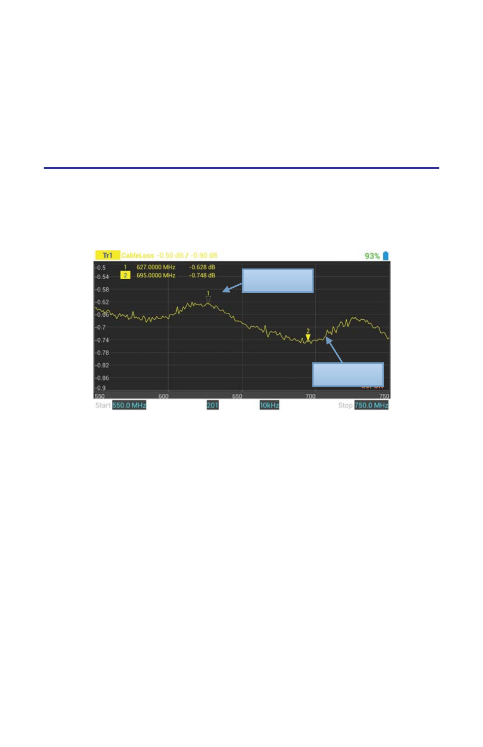
Interpreting a Cable Loss Measurement
The graph below shows a typical cable loss measurement. Note that the scale is
greatly reduced to show the cable’s variation across frequency.
Figure
10
Cable Loss Measurement Screen
Min. Loss
Max. Loss
1.
Take the average of M1 and M2.
Note:
This is the average cable loss across the frequency band.
2.
Compare the loss with the manufacturer’s specified loss for a cable of this
length.
Note:
If they do not correspond, retake the measurement, then
check the cable for problems.
- SK-4000-TC-Datasheet (2 pages)
- SH-36S-Manual (206 pages)
- SH-36S-Datasheet (4 pages)
- SH-36S-PC-Manual (130 pages)
- SH-36S-PC-Datasheet (2 pages)
- SH-36S-PC-Quick Start (2 pages)
- SH-36S-RM-Datasheet (2 pages)
- SA-3600XT-Manual (112 pages)
- SA-3600XT-Datasheet (2 pages)
- AT-500-Manual (73 pages)
- AT-500-Datasheet (2 pages)
- AT-800-Manual (74 pages)
- 89-83F-02-03-Manual (2 pages)
- 89-83F-02-03-Datasheet (1 page)
- 8251 Series-Datasheet (1 page)
- 8251 Series-Manual (30 pages)
- DA10 VHF Series-Datasheet (2 pages)
- DA10 VHF Series-Manual (47 pages)
- 8865SC13-Datasheet (2 pages)
- 8865SC13-Manual (28 pages)
- 8890-300SC13-Manual (28 pages)
- 8921SC13-Manual (28 pages)
- 8931-115SC13-Manual (34 pages)
- BDS-Datasheet (2 pages)
- BDS-Manual (98 pages)
- SCC7 Series-Datasheet (2 pages)
- SCC7 Series-Manual (45 pages)
- MSCC7 Series-Datasheet (2 pages)
- MSCC7 Series-Manual (35 pages)
- SCC8 Series-Datasheet (2 pages)
- SCC8 Series-Manual (47 pages)
- 4020 Series-Datasheet (1 page)
- 4020 Series-Manual (4 pages)
- 4027A Series-Datasheet (2 pages)
- 4027A Series-Manual (6 pages)
- 4027F Series-Datasheet (2 pages)
- 4027F Series-Manual (6 pages)
- 4028 Series-Datasheet (2 pages)
- 4028 Series-Manual (6 pages)
- 7022-Datasheet (4 pages)
- 7022-Manual (27 pages)
- ACM Series-Datasheet (2 pages)
- ACM Series-Manual (40 pages)
- BPME Series-Datasheet (4 pages)