Chapter 4 fault location mode, Selecting fault location mode – Bird Technologies SK-4000-TC-Manual User Manual
Page 29
17
Chapter 4
Fault Location Mode
Fault location identifies the position of impedance discontinuities (reflections)
within the antenna system. The measurement results are displayed on an x-y
graph. Distance from the SiteHawk Analyzer is shown on the x-axis, while rela-
tive magnitude of the discontinuity is shown on the y-axis.
Before making a fault location measurement, ensure that the following items
and information are present:
Calibration Combination (Cal Combo) calibration unit
All necessary cables and adapters of the correct size and connector type
The velocity of propagation for the cable type being measured (obtain
from the cable manufacturer)
Number of data points to use in making the distance to fault measure-
ment (user choice)
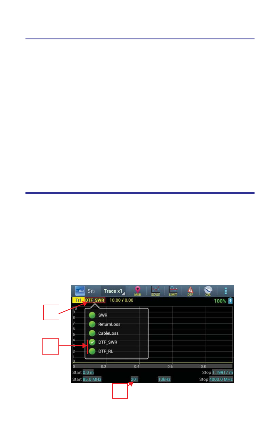
Selecting Fault Location Mode
1.
Select Mode.
2.
Select one of the following:
DTF_SWR
DTF_RL
Note:
When making a Cable Loss measurement, select units for the Y
(vertical) scale: DTF_SWR for standing wave ratio or DTF_RL for return
loss in dB.
3.
Select the number of Data Points.
Figure
11
DTF Mode Select
1
2
3