Bendix Commercial Vehicle Systems XVISION NIGHT VISION SYSTEM 8/11 User Manual
Page 8
8
AIMING ADJUSTER TOOL
The aiming adjuster tool is included with the
Bendix
®
X Vision
®
Night Vision System kit, but
cannot be ordered individually. It is the only tool that
should be used to install the IR camera onto the
aiming adjusters.
IR CAMERA/ DISPLAY COMBINATION
The IR camera and display are serviceable and can be
ordered individually. The IR camera/display combination
can be purchased as an entire XVision
system.
IR Camera (piece no. 5008214, service piece no.
801150) The IR camera must always be mounted externally
to the vehicle and attaches to the standoff pivot assembly
and aiming adjusters on the IR camera bracket. The IR
camera is operational within the range of -40°C to 60°C.
The IR camera has two electrical connections: a 6-pin
IR camera connector and a 2-pin window heater connector.
Video Display (piece no. 5010210, service piece no.
801154) – The display is operational within the range of
-40°C to 60°C. During power-up, the Bendix
®
icon will be
displayed in the combiner for approximately 45 seconds.
The intensity control will need to be adjusted according
to light conditions and driver preference. After the initial
warm-up, the IR camera’s field of view (FOV) will be
displayed in the combiner.
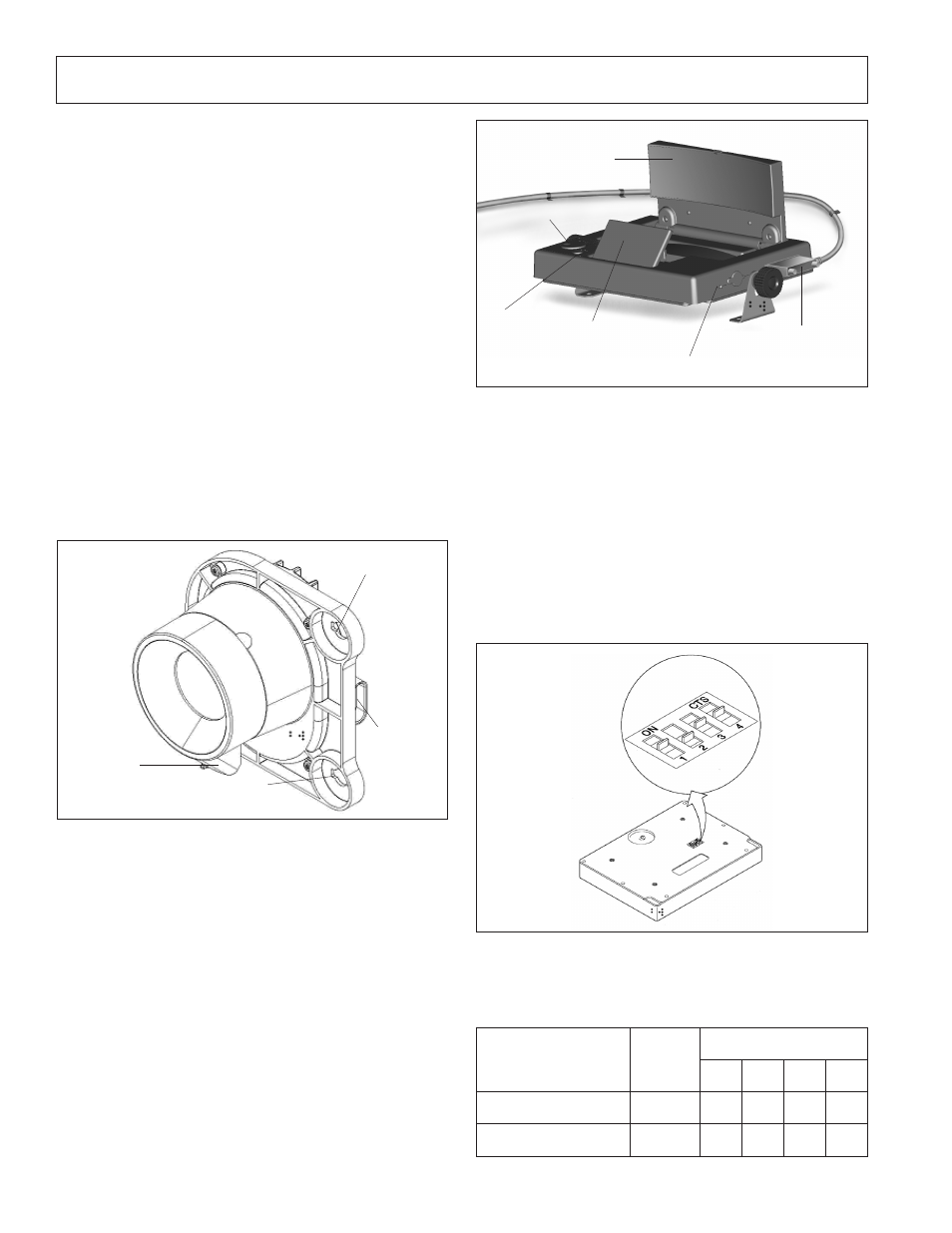
The orientation of the virtual image on the display will
depend on the display mounting style that you have chosen.
On the bottom of the display, under a switch cover, there
are four dual inline position (DIP) switches which allow you
to rotate or invert the image. To access the DIP switches,
slide the cover away from the 25-pin connector. Displays
arrive from the factory with the DIP switches configured
for the CB style dashboard mount. Refer to Table 5 for the
DIP switch settings appropriate for your mount.
FIGURE 14 - DISPLAY DIP SWITCHES FOR DASHBOARD
MOUNT
TABLE 5 - DIP SWITCH POSITIONS
Fold Mirror
Intensity
Control
Combiner
25-pin Connector
On/Off
Switch
Video In/Out Switch
FIGURE 13 - DISPLAY (SHOWN IN CB STYLE MOUNT
(DASHBOARD) POSITION WITH DISPLAY HARNESS)
Mounting Position
Video
Format
DIP Switch Positions
1
2
3
4
Dash Mounted
(NTSC) N/A OFF ON ON
Overhead Mounted (NTSC) N/A OFF OFF OFF
Window Heater
Connection
Aiming
Adjuster
Mounting
IR Camera
Connection
Standoff Pivot Mounting
FIGURE 12 - IR CAMERA
Parts/kits listed are now obsolete and are no longer serviceable through Bendix.