Bendix Commercial Vehicle Systems XVISION NIGHT VISION SYSTEM 8/11 User Manual
Page 20
20
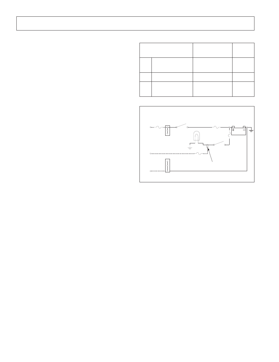
Battery
Headlamp
Headlamp
Switch
1 AMP fast
open fuse
Ignition
Switch
3 AMP slow
open fuse
Black
Wire
Blue
Wire
Red
Wire
A
C
B
Ignition
bus
Ground
Bus
Butt
Splice
27. Re-install the headliner and the “A” pillar cover.
28. Turn on the system to verify that it is operating
correctly.
29. Aim and adjust the IR camera. Refer to
Aiming the
IR Camera on pages 20 and 21.
Display Harness
1. Unscrew and disconnect the 25-pin connector of the
display harness.
2. Remove the trim pieces covering the harness.
3. Disconnect the display harness from the 8-pin
IR camera harness connector and the 3-pin vehicle
harness connector.
4. Remove any fasteners securing the display harness.
5. Connect the new display harness as follows:
•
the 3-pin connector to the vehicle harness.
•
the 8-pin connector to the IR camera harness.
•
the 25-pin connector to the display.
6. Turn on the system to verify that it is operating correctly.
7. Replace the “A” pillar cover.
8. Secure the new display harness every 3 in. with
cable ties.
Vehicle Harness
WARNING: Improper installation of the vehicle
harness can cause damage to your vehicle’s wiring
and/or to the Bendix
® X
Vision
®
Night Vision System.
It is the responsibility of the installer to review wiring
and service information for the vehicle and to identify
proper locations for connecting the vehicle harness
to the power. Many modern vehicles have additional,
built-in fused accessory power breakouts and these
breakouts should be used if at all possible.
1. Remove the trim pieces covering the harness.
2. Disconnect the vehicle harness from the display
harness.
3. Remove the red wire (A-contact) from the ignition bus.
4. Remove the blue wire (C-contact) that is butt-spliced
between the headlamp and the headlamp switch.
5. Remove the black wire (ground) from the ground bus.
6. Remove any fasteners securing the vehicle harness.
7. Remove the old vehicle harness.
8. Strip the three ends of the new vehicle harness.
9. Connect the red wire (A-contact) of the new vehicle
harness to the ignition bus with a 3 A slow open fuse.
10. Butt splice the blue wire (C-contact) of the new vehicle
harness between the headlamp and the headlamp
switch with a 1 A fast open fuse.
11. Connect the black wire to the ground bus.
12. Route the new vehicle harness to the display harness
and connect them.
13. Turn the system on to verify that it is operating
correctly.
14. Secure the new vehicle harness every 6-12 in. with
cable ties.
15. Replace the “A” pillar cover.
Jumper Harness
1. Remove any fasteners securing the jumper harness.
2. Disconnect the jumper harness from the IR camera
harness and the display harness.
3. Connect the replacement jumper harness to the IR
camera harness and the display harness.
4. Turn the system on to verify that it is operating correctly.
5. Secure the new jumper harness every 6-12 in. with
cable ties.
TABLE 6 - VEHICLE HARNESS WIRING
Vehicle Harness
Connector 3 Contacts
Fused
Color
A
Vehicle ignition
+12 Volts
3 A slow open fuse
(max.)
RED
B
Vehicle ground
BLACK
C
Headlamp active 1 A fast open fuse
(max.)
BLUE
FIGURE 34 - XVISION SYSTEM ELECTRICAL POWER
SCHEMATIC
Parts/kits listed are now obsolete and are no longer serviceable through Bendix.