Bendix Commercial Vehicle Systems BRAKE CHAMBERS User Manual
Bendix
1
®
Bendix
®
Brake Chambers
SD-02-1302
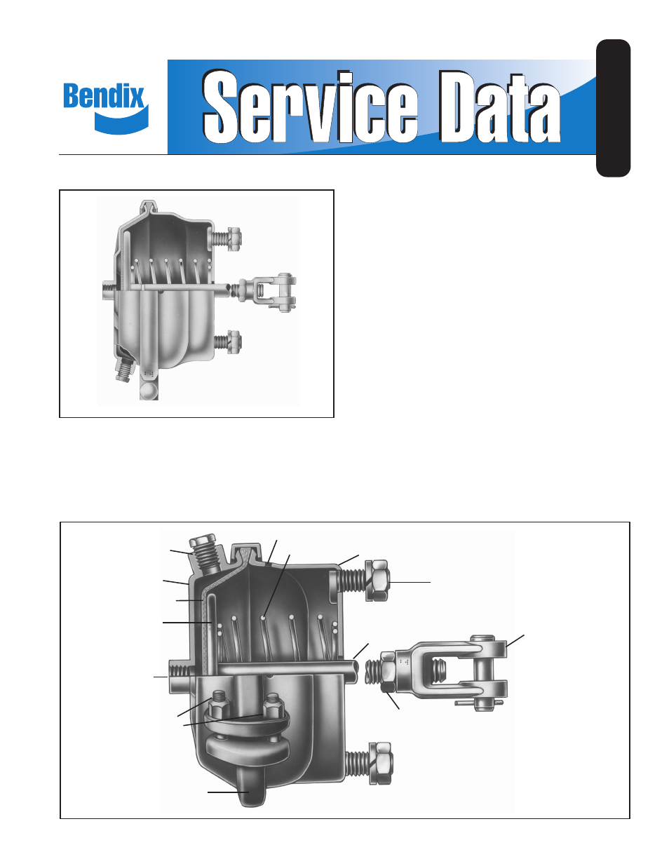
Clamp Ring (C)
Push Plate and Push
Rod Assy.
Clamp Ring Nuts
& Bolts
Center Inlet Port
Non-Pressure Plate (B)
Spring
Vent
Side Inlet Port
(shown plugged)
Pressure Plate (A)
Diaphragm
Push Plate
DESCRIPTION
The brake chamber is a diaphragm-type actuator which
converts the energy of air pressure into mechanical force.
See Figure 2. The diaphragm is held between the pressure
plate (A) and non-pressure plate (B) by either a one- or
two-piece clamp ring (C).
Different size brake chambers are identified by numbers
which specify the effective area of the diaphragm. For
example, a brake chamber that has 30 square inches of
“effective area” (the area of the diaphragm that generates
force on the push plate), is commonly referred to as a type
30 brake chamber. See Figure 2.
Since one side of a brake chamber diaphragm is exposed to
the applying air pressure and the other side to atmospheric
pressure, the chamber has a pressure and a non-pressure
side. The non-pressure plate is usually vented to
atmosphere by vent holes. Installations where the chamber
must be weather-proof, venting is accomplished through a
variety of methods. Consult the OEM for specific details.
The standard diaphragm material is a compound of natural
rubber with a fabric interior of nylon. Neoprene-nylon
diaphragms are optionally available.
OPERATION
Controlled air pressure enters the brake chamber through
the inlet port and acts upon the diaphragm moving the push
plate and rod assembly forward.
Lock Nut
Yoke
Mounting
Bolts
FIGURE 2 - CUT-AWAY VIEW
FIGURE 1 - BENDIX
®
BRAKE CHAMBER