Aiming the ir camera – Bendix Commercial Vehicle Systems XVISION NIGHT VISION SYSTEM 8/11 User Manual
Page 21
21
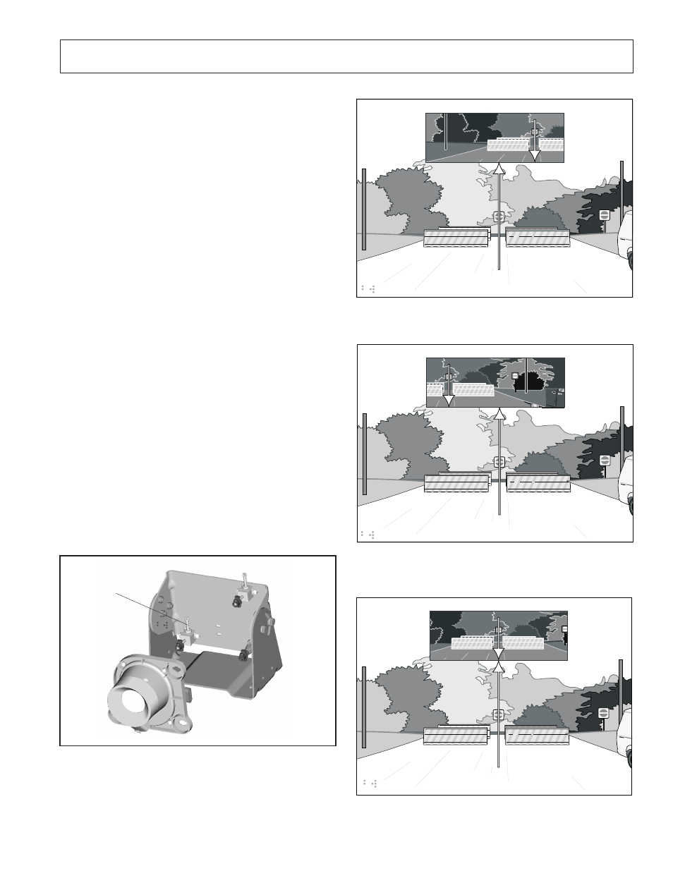
FIGURE 38 - IR CAMERA AIMED CORRECTLY
AIMING THE IR CAMERA
The aiming adjusters on the IR camera bracket allow the
forward field of view (FOV) of the IR camera to be adjusted
horizontally and vertically. The adjustment screw head(s)
will accommodate an E8 external Torx
®
or a T15 internal
Torx
®
.
When the IR camera is mounted, adjust the horizontal and
vertical aiming adjusters to align the IR camera FOV with
the display. The position of the virtual image on the display
and how the virtual image correlates to objects in the road
depends directly on IR camera aiming.
NOTE:
Use two people to aim and adjust the IR
camera. One technician should view the virtual image
on the display while the other technician aims the IR
camera.
NOTE: Verify that the vehicle is level and that the
tires are properly inflated before beginning the IR
camera aiming procedure.
HORIZONTAL AIMING AND ADJUSTING
When the IR camera is not mounted directly above the
driver, the angle of the IR camera will need to be adjusted.
Align the display image horizontally with the objects in the
road to give the driver a sense of object location.
1. Using Figures 35-38 and a T15 Torx wrench, adjust the
angle of the IR camera as needed.
NOTE: Two and one-quarter turns of the horizontal
adjuster is equal to one degree of IR camera
movement.
NOTE: Do not tamper with or adjust any
factory-installed screws while aiming the camera.
Only turn the horizontal aiming adjuster.
Horizontal
Aiming Ad-
juster
FIGURE 35 - HORIZONTAL AIMING ADJUSTER
Combiner Image
Driver’s View
FIGURE 36 - IR CAMERA AIMED TOO FAR LEFT
Combiner image
Driver’s View
FIGURE 37 - IR CAMERA AIMED TOO FAR RIGHT
Combiner image
Driver’s View
Parts/kits listed are now obsolete and are no longer serviceable through Bendix.