Bendix Commercial Vehicle Systems XVISION NIGHT VISION SYSTEM 8/11 User Manual
Page 13
13
Replacing the Aiming Adjusters
1. Unlock the IR camera by turning the two IR camera
aiming adjusters and the IR camera standoff
1/4 turn counterclockwise.
2. Remove the IR camera from the IR camera bracket to
get easier access to the connectors.
3. Disconnect the 6-pin IR camera connector and the 2-pin
window heater connector of the IR camera harness
from the IR camera. Cut the cable tie to allow access.
Refer to Figure 24.
6. Replace the damaged parts with the new aiming
adjusters and standoff pivot assembly that were
received with the service kit (piece no. 5010079).
NOTE: The IR camera bracket can only be ordered
as a component of the IR camera bracket kit.
However, the components that attach to the IR
camera bracket to aim and adjust the IR camera can
each be ordered in the aiming adjuster replacement
kit. The kit includes the items below.
Standoff pivot assembly (QTY 1) – fastens to the
IR camera standoff base with a maximum torque of
16 in-lbs.
Standoff base (QTY 1) – fastens to the IR camera
bracket with #10 Plastite
®
Hex
®
flange head
screw and lockwasher with a maximum torque of
18-20 in-lbs.
Aiming adjusters (QTY 2) – latch the IR camera
into position on the IR camera bracket and allow the
IR camera forward FOV to be adjusted horizontally
and/or vertically. The adjustment screw head(s)
accommodate an E8 external Torx
®
or a T15 internal
Torx
®
tool. (The aiming adjusters are fastened to the
IR camera bracket and torqued to 18 in-lbs. with four
#8-32
Hex
®
/Torx
®
screws.
7. Install the new aiming adjuster(s) using the #8-32
Hex
®
/Torx
®
screws. Torque the screws to 18 in-lbs.
8. Install the new standoff pivot assembly using the #10
lock washer and Plastite
®
Hex
®
flange head screw.
Torque the screw to 16 in-lbs.
4. Remove the #8-32 Hex
®
/Torx
®
screws from the
damaged aiming adjuster(s). Refer to Figure 25.
5. Remove the Plastite
®
Hex
®
flange head screw and #10
lock washer from the damaged standoff pivot assembly.
FIGURE 24 - CONNECTING THE CAMERA HARNESSES
Cable Tie
6-pin connector
2-pin connector
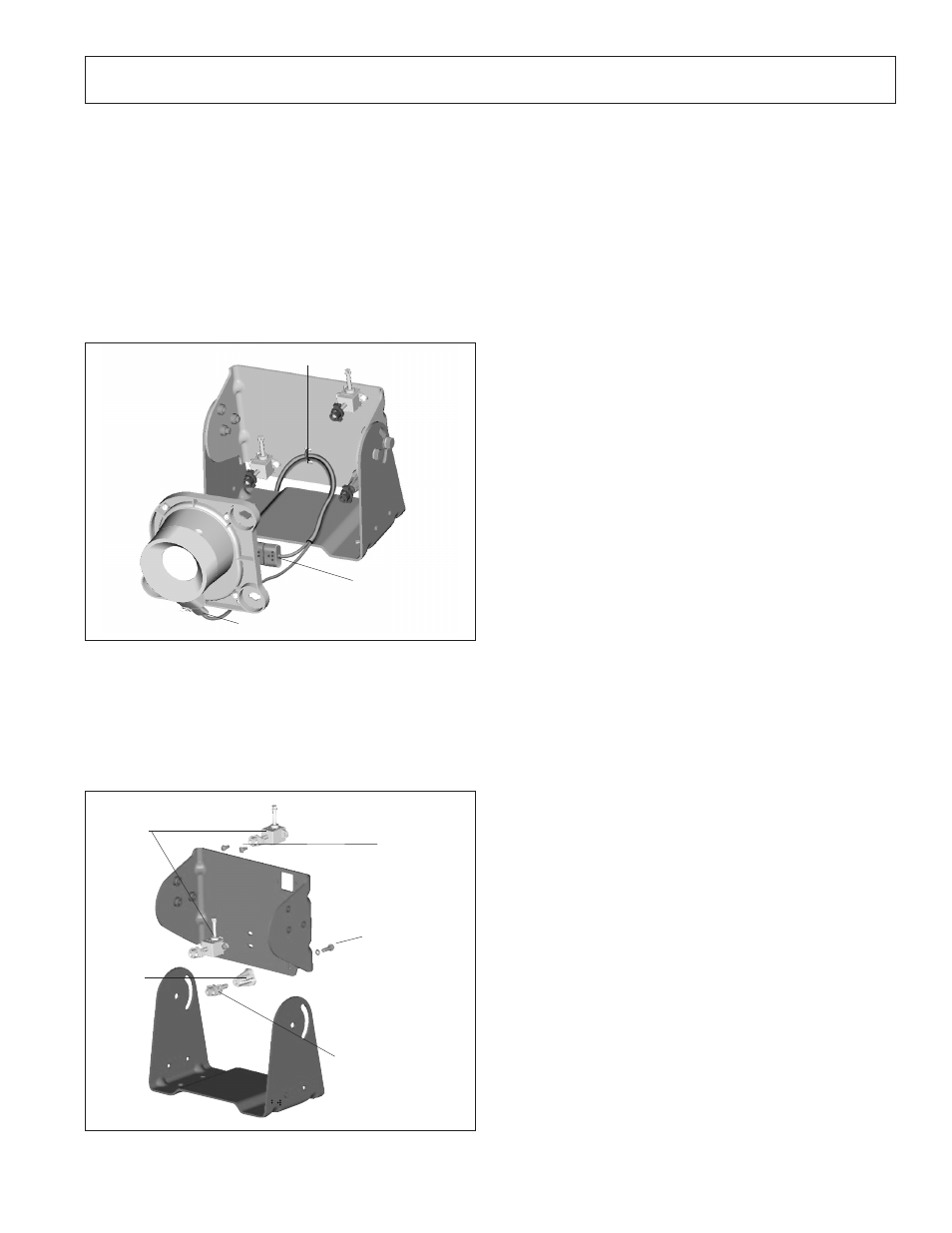
FIGURE 25 - AIMING ADJUSTER REPLACEMENT
KIT COMPONENTS
Standoff Pivot
Assembly
(16 in-lbs.)
Standoff
Base
Aiming
Adjusters
#8-32
Hex
®
/ Torx
®
(18
in-lbs.)
#10 Plastite
®
Hex
®
flange with lock
washer
(18-20 in-lbs.)
Parts/kits listed are now obsolete and are no longer serviceable through Bendix.