Servicing the xvision, System, Electrical system – Bendix Commercial Vehicle Systems XVISION NIGHT VISION SYSTEM 8/11 User Manual
Page 10: Power and ground (power inputs), Operating input voltage
10
SERVICING THE XVISION
SYSTEM
The following sections provide instructions for maintaining
and/or replacing components of the XVision system.
CAMERA MOUNTING BRACKET REPLACEMENT
1. Loosen and remove the four 5/16 in. bolts securing
the IR camera bracket to the mounting bracket.
2. Disconnect the camera harnesses (2-pin and 6-pin).
Remove the IR camera assembly.
3. From inside the cab, remove all mounting hardware
from the mounting bracket.
4. Remove the stud plates, mounting bracket, and shims
(if used).
5. Clean the area around the drilled holes in the cab.
6. Align the new mounting bracket with the holes in
the cab. Note: use new mounting hardware for the
installation.
Battery
Headlamp
Headlamp
Switch
1 AMP fast
open fuse
Ignition
Switch
3 AMP slow
open fuse
Black
Wire
Blue
Wire
Red
Wire
A
C
B
Ignition
bus
Ground
Bus
Butt
Splice
ELECTRICAL SYSTEM
POWER AND GROUND (POWER INPUTS)
Electrical power to the Bendix
®
XVision
®
Night Vision
System is provided through the vehicle harness. The
vehicle ignition wire {(A) Red} should be fused to a 3 A
slow open fuse (maximum) and connected to the ignition
bus of the vehicle. The ground wire {(B) black} should be
connected to the ground bus of the vehicle. The headlamp
active wire {(C) blue} should be fused to a 1 A fast open
fuse (maximum) and connected to the vehicle headlamp
circuit. When the headlamps are on, 12V should be present
on the blue wire.
WARNING: Vehicle power and headlight circuits
MUST be fused. Permanent damage to the display,
IR camera, or vehicle electrical system could occur
if power to these units is not fused. Eliminating fuses
from circuit will void all warranties.
IMPORTANT: When replacing a fuse, it is important
to use only the specified fuse with the correct
amperage, as listed above. The use of a fuse with a
rating other than indicated may result in a dangerous
electrical system overload. Repeated opening of a
properly rated fuse indicates a problem in the circuit
that must be corrected.
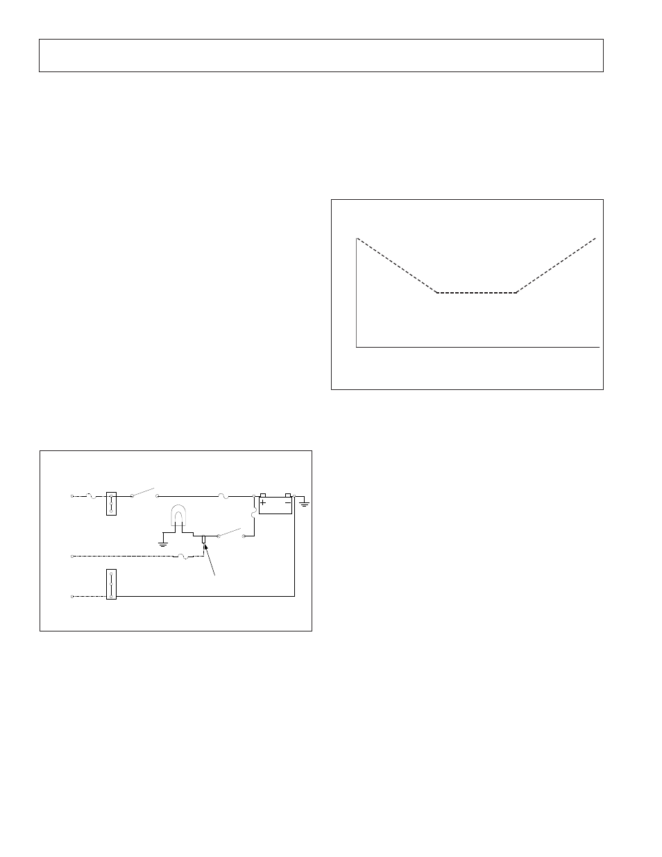
OPERATING INPUT VOLTAGE
The IR camera is operational in the temperature range
between -40°C to 60°C. Normally, the IR camera takes
about 45 seconds to warm up. However, as the external
temperature gets closer to the extremes listed, the warm-up
time will begin to approach two minutes. Refer to Figure 19.
The IR camera and display are compatible with 12V DC
battery systems with a chassis ground.
FIGURE 19 - OPERATIONAL TEMPERATURE RANGE AND
WARM-UP TIME OF IR CAMERA
1
2
-40
0
40
60
Temperature (Celsius)
Time (minutes)
FIGURE 18 - XVISION
SYSTEM ELECTRICAL SCHEMATIC
Parts/kits listed are now obsolete and are no longer serviceable through Bendix.