Bendix Commercial Vehicle Systems XVISION NIGHT VISION SYSTEM 8/11 User Manual
Page 14
14
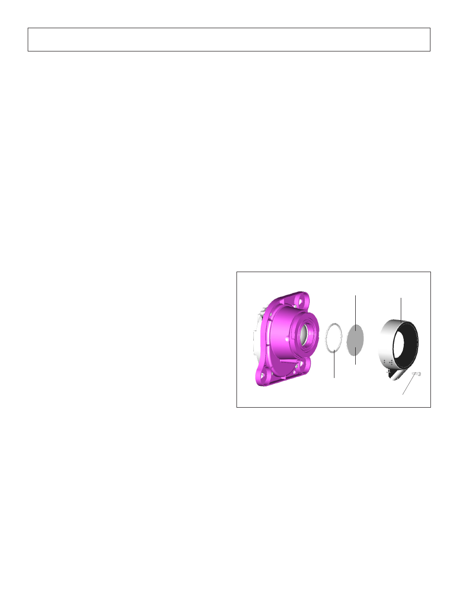
Bezel Retaining
Plug
FIGURE 26 - IR CAMERA WINDOW AND BEZEL
RETAINING PLUG
IR Camera
IR Camera
Window
IR Camera Win-
dow Seal
Bezel Heater As-
sembly
IR CAMERA WINDOW
Maintaining
The IR camera window, a 1.3 mm thick silicon disk, is an
optical element and should be cleaned when it becomes
dirty or filled with debris. Dirt and debris can affect the
IR camera performance.
To clean the window, use a soft, damp cloth moistened with
window cleaning solution. Shop rags and paper towels will
scratch optical surfaces.
NOTE: The IR camera heater cannot melt large
amounts of packed snow in the window area. It is
recommended that the snow be removed manually
prior to system operation. When cleaning ice or
snow from the IR camera, use a commercially
available spray deicer; do not use scrapers or sharp
instruments that may scratch or break the window.
Replacing
If the window cracks or breaks, it must be replaced.
1. Unlock the IR camera assembly by turning the two
IR camera aiming adjusters and the standoff pivot
assembly 1/4 turn counterclockwise.
2. Remove the IR camera from the IR camera bracket
to gain easier access to the connectors.
3. Disconnect the 6-pin IR camera connector and the
2-pin window heater connection of the IR camera
harness from the IR camera.
4. Lay the IR camera face-up for easy access to the
bezel retaining plug. Refer to Figure 26.
5. Remove the bezel retaining plug.
6. Turn the bezel heater assembly 1/4 turn
counterclockwise, until it separates from the IR
camera.
7. Replace the damaged window and seal.
NOTE: The replacement window is treated with a
black scratch-resistant coating on one side only. The
side that appears black must face the environment.
NOTE: If the area between the IR camera window
and IR camera lens is contaminated because of
a damaged seal or window, carefully remove the
contamination. If a window cleaning solvent is
used to clean the area, be sure to remove all of the
moisture from the sealed cavity before assembling
the o-ring seal and window. Moisture remaining in
the sealed area will affect the performance of the IR
camera.
NOTE: Use care when removing shards of glass.
8. Turn the bezel heater assembly 1/4 turn clockwise to
reattach it to the IR camera. Note: Ensure the window
is positioned correctly or it can be damaged when
installing the bezel.
9. Lock the bezel heater assembly in place with the bezel
retention plug.
10. Plug the 2-pin connector of the IR camera harness into
the window heater. Refer to Figure
24 on page 12.
11. Plug the 6-pin connector of the IR camera harness
into the IR camera connection. Refer to Figure
24 on
page 12.
12. Position the IR camera onto the factory-installed
aiming assemblies.
13. Rotate the pivot locks on the end of the aiming
assemblies 1/4 turn clockwise, using the aiming
adjuster tool. This will lock the IR camera in position.
14. Aim and adjust the IR camera. Refer to
Aiming the
IR Camera on pages 21 and 22.
Black side
Parts/kits listed are now obsolete and are no longer serviceable through Bendix.