Rockwell Automation 1440-SPD02-01RB XM-220 Dual Speed Module User Manual
Page 57
Publication GMSI10-UM004B-EN-P - May 2010
Configuration Parameters 49
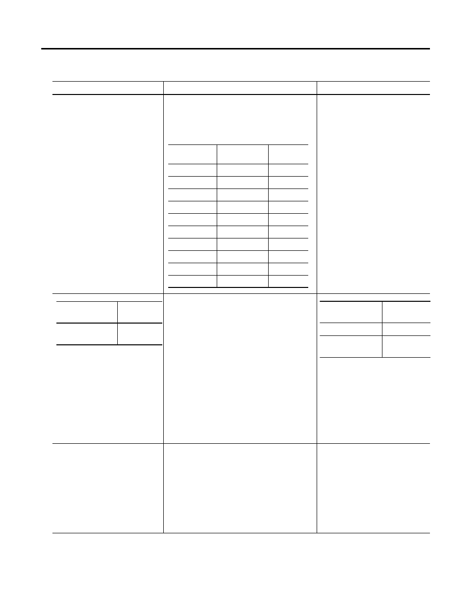
DC Bias Time Constant
The time constant used for exponential averaging
(low pass filtering) of the transducer DC bias
measurement. The corner frequency for the low pass
filter is 1 / (2 x
π
x DC Bias Time Constant). See
example table below.
Seconds
Sets the trigger mode. In Auto Trigger mode, the
minimum signal amplitude for triggering is 2 volts
peak-to-peak and minimum frequency is 6 CPM (0.1
Hz).
In Manual Trigger mode, the value entered in
Trigger Threshold is used as the trigger point.
Minimum signal amplitude for triggering is 500
millivolts peak-to-peak and minimum frequency is 1
CPM (0.0167 Hz).
Important: If you are using Auto
Trigger mode with passive magnetic
sensors, make certain to enable the
Bias Current parameter (see page
48). The bias current parameter
adjusts the auto-trigger detection
algorithm for passive magnetic
signals.
Trigger Hysteresis
The amount of hysteresis around the trigger
threshold. In Auto Trigger mode, the value entered is
a percentage of the peak-to-peak input signal. This
value can range from 0 to 50%.
In Manual Trigger mode, the value entered is a
voltage level. The hysteresis voltage is added to or
subtracted from the threshold voltage to determine
the hysteresis range. The minimum value is 0.12
volts.
% in Auto Trigger mode
Volt in Manual Trigger mode
Tachometer Parameters
Parameter Name
Description
Values/Comments
Time Constant
(seconds)
-3dB Frequency
(Hz)
Settling
(seconds)
1
0.159
2.2
2
0.080
4.4
3
0.053
6.6
4
0.040
8.8
5
0.032
11
6
0.027
13.2
7
0.023
15.4
8
0.020
17.6
9
0.018
19.8
10
0.016
22
XM Configuration
Utility
EDS File
Auto Trigger
Trigger
Mode
XM Configuration
Utility
EDS File
Check = Auto Mode
Auto
Clear = Manual
Mode
Manual