Connecting the startup switch, Connecting the transducer – Rockwell Automation 1440-SPD02-01RB XM-220 Dual Speed Module User Manual
Page 37
Publication GMSI10-UM004B-EN-P - May 2010
Installing the XM-220 Dual Speed Module 29
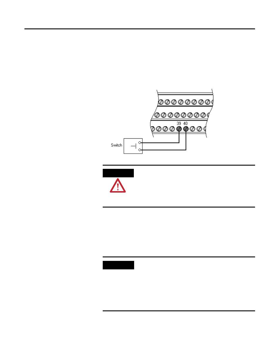
Connecting the Startup Switch
You can configure the module to detect a locked rotor condition or inhibit the
tachometer fault alarm status during the start-up period. Wire the Startup
switch to the terminal base unit as shown in Figure 2.18.
Figure 2.18 Startup Switch Connection
Connecting the Transducer
The XM-220 can accept input signals from any Allen-Bradley non-contact
eddy current probe, magnetic pickups, or TTL output devices.
ATTENTION
The Switch Input circuits are functionally isolated from
other circuits. It is recommended that the Switch RTN
signal be grounded at a signal point. Connect the Switch
RTN signal to the XM terminal base (Chassis terminal) or
directly to the DIN rail, or ground the signal at the switch
or other equipment that is wired to the switch.
IMPORTANT
Active magnetic speed sensors or eddy current probes are
often used on machines where rotational speeds below 250
rpm must be reliably sensed, for example reverse rotation
and zero speed applications. Passive magnetic speed
sensors do not typically generate a suitable signal at slow
shaft rotational speeds. To sense shaft rotation speeds
down to 1 rpm, active magnetic speed sensors or eddy
current probes are required.