Connecting a magnetic pickup sensor, Figure 2.20 non-contact sensor to channel 2 wiring, Important – Rockwell Automation 1440-SPD02-01RB XM-220 Dual Speed Module User Manual
Page 39
Publication GMSI10-UM004B-EN-P - May 2010
Installing the XM-220 Dual Speed Module 31
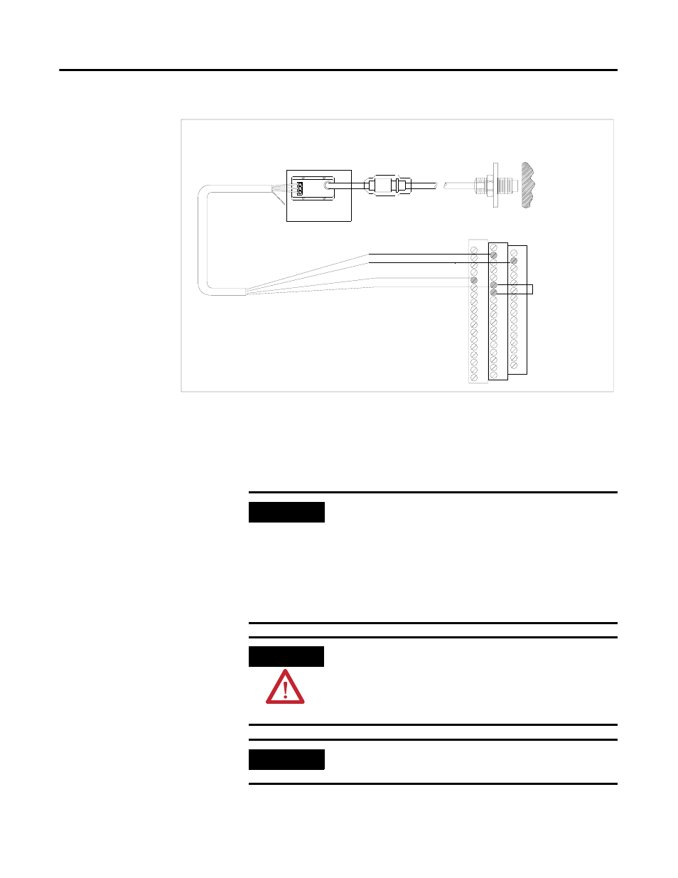
Figure 2.20 Non-contact Sensor to Channel 2 Wiring
Connecting a Magnetic Pickup Sensor
The figures below show the wiring of a passive magnetic pickup sensor to the
terminal base unit.
TYPICAL WIRING FOR NON-CONTACT SENSOR
TO XM-220 DUAL SPEED MODULE CHANNEL 2
COM
SIG
-24
Channel 2 Input Signal
-24V DC
1
17
Signal Common
21
22
Jumpering terminal
21 to terminal 22
configures CH 2 buffer
for -24V to 9V
Isolated Sensor Driver
Shield
Shield
Floating
38
IMPORTANT
Active magnetic speed sensors or eddy current probes are
often used on machines where rotational speeds below 250
rpm must be reliably sensed, for example reverse rotation
and zero speed applications. Passive magnetic speed
sensors do not typically generate a suitable signal at slow
shaft rotational speeds. To sense shaft rotation speeds
down to 1 rpm, active magnetic speed sensors or eddy
current probes are required.
ATTENTION
You may ground the cable shield at either end of the cable.
Do not ground the shield at both ends. Recommended
practice is to ground the cable shield at the terminal base
and not at the transducer. Any convenient Chassis terminal
may be used (see Terminal Block Assignments on page 18).
IMPORTANT
The module does not power the sensor. It measures only
the input voltage.