Rockwell Automation GV3000/SE V.6 Regulator Board 0-56921-6xx, 413338-6BU, 0-56940-6xx, 814.61.00 User Manual
Page 60
Installing Regulator Board P/N 413338-6BU in 60 to 100 HP and 100 to 150 HP @ 460 VAC Drives
8-7
Step 4.
Remove the Regulator Board from the Keypad Bracket
Step 4.1. Drives with option boards only: Remove the option board from the keypad
bracket. The option board is held in place by four fasteners.
Step 4.2. Drives with option boards only: Remove the Regulator board ribbon
connector from the option board. The connector is held in place by retaining
clips. Spread these clips to release the connector.
Step 4.3. Remove the Regulator board from the keypad bracket by removing the four
screws and hex nuts.
Step 4.4. Slide the old Regulator board out of the keypad bracket.
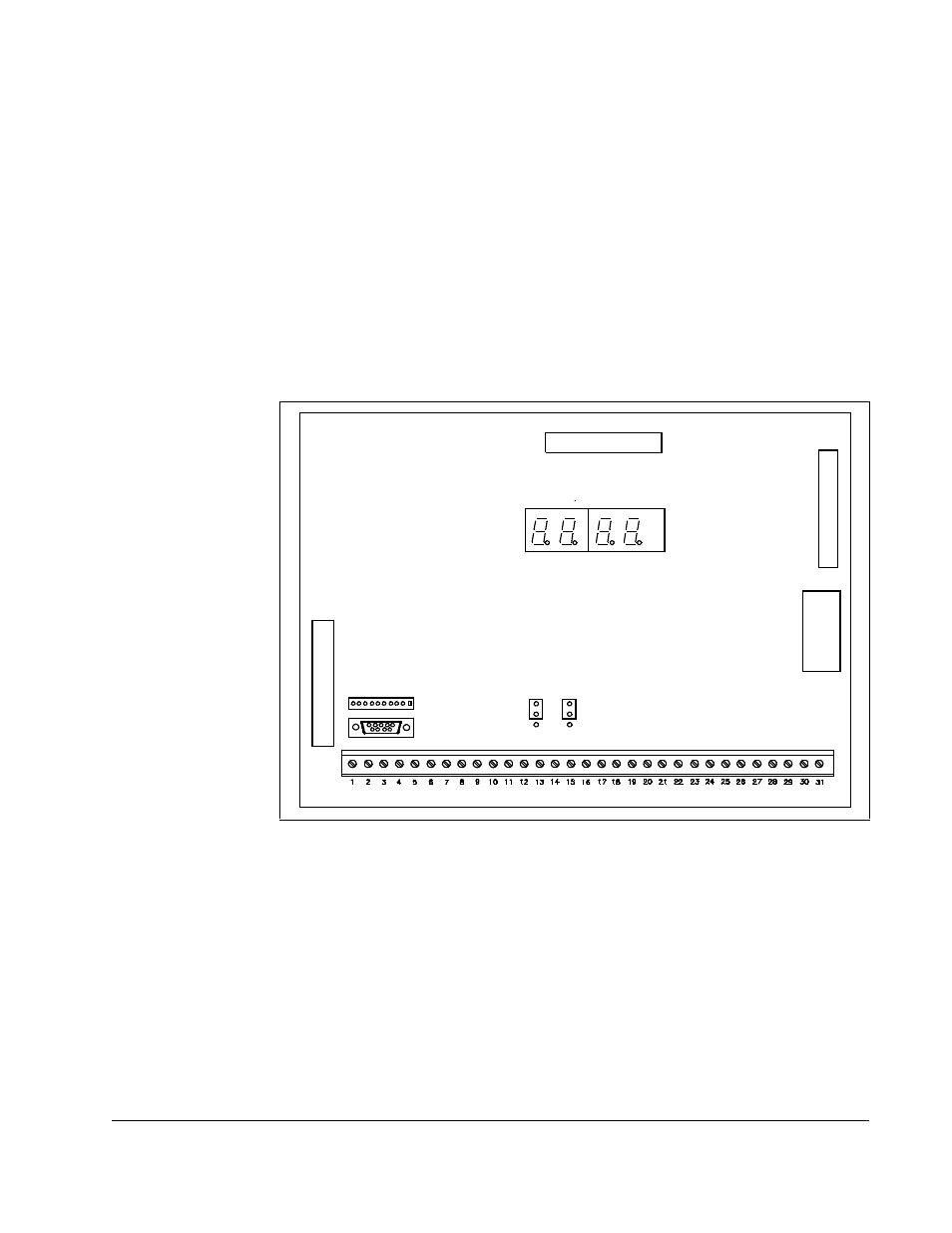
Step 4.5. Note the settings of jumpers J4 and J17 on the old Regulator board. These
jumpers are above the center of the terminal strip as shown in figure 8.6.
Step 5.
Install the New Regulator Board in the Keypad Bracket
Step 5.1. Remove the new Regulator board from its anti-static wrapper. Make sure
the jumper settings on the new board match those on the old board.
Step 5.2. Slide the new Regulator board into the keypad bracket. Position the board
so that seven-segment displays appear in the display window in the keypad.
Step 5.3. Mount the new Regulator board to the keypad bracket using the screws and
hex nuts removed earlier.
Step 5.4. Drives with option boards only: Align the key on the Regulator board’s
34-conductor ribbon cable connector with the slot in the option board
connector. Press the ribbon cable connector in until it locks into position.
Figure 8.6 – Location of Jumpers J4 and J17 on the Regulator Board
34
-P
in
R
ibb
on
C
a
bl
e
J8
J4
J17
USER I/O TERMINAL STRIP
26
-Pin
R
ibbo
n
C
a
b
le
J5
J9
J3
J7
USER DISPLAY
60-Pin Ribbon Cable
J16